Definition: A galvanometer is a sensitive electrical measuring instrument used to detect the presence and direction of small electric currents in a circuit. It can also indicate small voltage differences by producing a deflection of its pointer. Galvanometers are commonly used in electrical measuring circuits, particularly in bridges and potentiometers, to detect the null condition (zero current or zero deflection) during measurements.
Construction of the Galvanometer
The construction diagram of Galvanometer is shown in the image below.
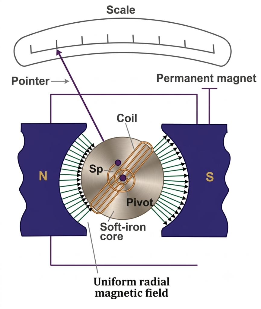
Main Parts of a Galvanometer
A galvanometer consists of several important components that work together to detect and measure small electric currents. The main parts include the moving coil, suspension, permanent magnet, mirror, and torsion head. Each component performs a specific function in the operation of the instrument.
1. Moving Coil
The moving coil is the current-carrying element of a galvanometer. It is generally rectangular or circular in shape and consists of several turns of fine insulated copper wire.
The coil is placed between the poles of a permanent magnet and is free to rotate about its vertical axis. When current passes through the coil, it experiences a deflecting torque due to the magnetic field. A soft iron core is provided inside the coil to produce a strong and uniform magnetic field by offering a low-reluctance path for magnetic flux.
2. Suspension
The suspension supports the moving coil and allows it to rotate freely. It generally consists of a thin, flat metallic ribbon made of gold or copper, which also carries current to the moving coil.
A lower suspension or conducting spring provides the return electrical connection. The upper suspension also produces the controlling torque required to oppose the coil’s deflection.
Since the suspension ribbon is delicate and has limited mechanical strength, the galvanometer should be handled carefully. Sudden jerks and mechanical shocks can damage it.
3. Mirror
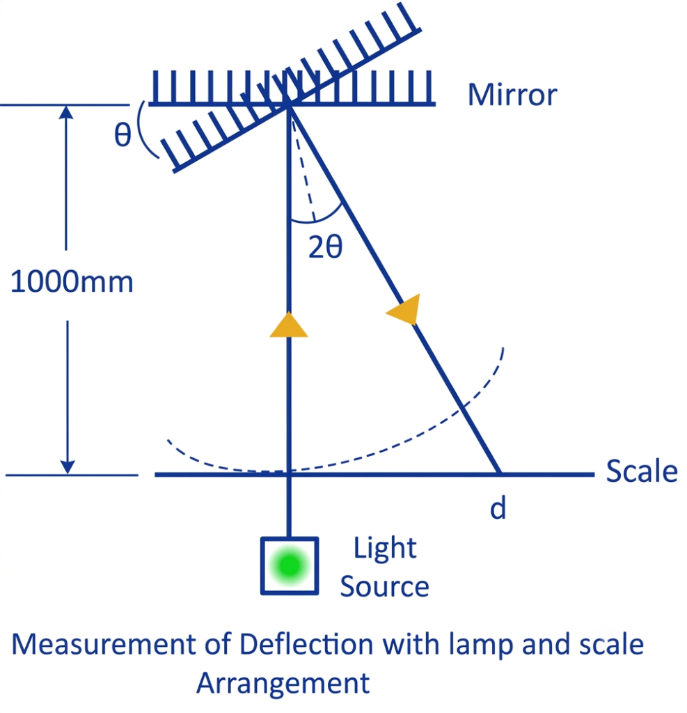
A small mirror is attached to the suspension system of a sensitive galvanometer. It is used in conjunction with a light source and a graduated scale to measure the angular deflection of the moving coil.
A beam of light is directed towards the mirror and reflected onto the scale. When the coil rotates, the mirror also changes its position, causing the reflected light spot to move along the scale. This arrangement helps measure very small current-induced deflections accurately.
4. Torsion Head
The torsion head is a mechanical adjustment provided at the upper end of the galvanometer suspension. It is used to adjust the position of the moving coil and set the instrument to its zero position.
By rotating the torsion head, the tension in the suspension ribbon can be adjusted, which changes the controlling torque acting on the moving system. This helps obtain the required zero setting before taking measurements.
Working Principle of Galvanometer
A galvanometer works on the principle that a current-carrying coil placed in a magnetic field experiences a mechanical torque. This torque causes the coil to rotate, and the resulting deflection indicates the magnitude and direction of the electric current flowing through it.
When the galvanometer is connected to an electrical circuit, current passes through its moving coil. Since the coil is positioned between the poles of a permanent magnet, the interaction between the magnetic field and the current-carrying coil produces a deflecting torque.
As a result, the coil starts rotating about its axis. The suspension system or control springs attached to the coil develop a restoring torque that opposes this rotation. As the coil turns further, the restoring torque increases.
The coil eventually reaches an equilibrium position when the deflecting torque becomes equal to the restoring torque. At this point, the coil stops rotating, and the pointer or reflected light spot indicates the current value on the calibrated scale.
The deflection of the coil is directly proportional to the current flowing through it, provided the instrument operates within its normal working range. Therefore, a galvanometer can detect small currents and indicate their direction.
Important: A galvanometer is a sensitive instrument designed to measure small currents. Passing excessive current through its moving coil can cause overheating and permanent damage. To protect the instrument when measuring larger currents, a low-resistance shunt is connected in parallel with the galvanometer coil. This diverts most of the current through the shunt and allows only a small, safe portion to pass through the coil.
Working of Galvanometer
The working of a galvanometer can be understood by analysing the deflecting torque produced when current flows through its moving coil and the restoring torque developed by the suspension.
Consider a rectangular moving coil placed in the magnetic field of a permanent magnet. When electric current passes through the coil, a deflecting torque acts on it, causing the coil to rotate. The suspension produces an opposing torque until the coil reaches its final steady-state position.
Let us consider the following symbols:
- – Lengths of the respective vertical and horizontal sides of the coil.
- – Number of turns in the coil.
- – Flux density in the air gap, Wb/m².
- – Current flowing through the moving coil in amperes.
- – Spring constant of suspension, Nm/rad.
- – Final steady-state deflection of the moving coil in radians.
1. Deflecting Torque
When current flows through the moving coil placed in a magnetic field, each active vertical side of the coil experiences a mechanical force.
The force acting on each side of the coil is given by:
Where is the number of turns, is the magnetic flux density, is the current, and is the length of the vertical side.
Since the forces acting on the opposite sides of the coil are equal and opposite, they form a couple that produces a deflecting torque.
The deflecting torque is:
Therefore,
Since the area of the rectangular coil is:
The deflecting torque can also be expressed as:
Where represents the area of the coil.
2. Galvanometer Displacement Constant
For a given galvanometer, the number of turns (N), magnetic flux density (B), and coil area (A) remain constant.
Therefore, we can write:
Where is called the displacement constant of the galvanometer.
Thus, the deflecting torque becomes:
3. Controlling Torque
When the moving coil rotates, the suspension twists and develops a restoring torque. This torque acts in the opposite direction to the deflecting torque and prevents unlimited rotation of the coil.
The controlling torque exerted by the suspension at a deflection of is:
Where:
- = Spring constant of suspension.
- = Angular deflection in radians.
4. Final Steady-State Deflection
When the coil reaches its final steady position, the deflecting torque becomes equal to the controlling torque.
Therefore,
Substituting the respective torque equations:
Rearranging,
Since , the final deflection can also be written as:
This equation indicates that the angular deflection of a galvanometer is directly proportional to the current flowing through its moving coil.
5. Deflection of the Reflected Light Beam
In a mirror-type galvanometer, a small mirror is attached to the suspension system. A beam of light is reflected from this mirror onto a graduated scale.
When the moving coil and mirror rotate through an angle , the reflected light beam turns through an angle of .
For small deflection angles, the displacement of the reflected light spot on the scale is given by:
Where is the distance between the mirror and the scale.
If the distance is 1000 mm:
Substituting :
Therefore,
This equation shows that the displacement of the reflected light beam is proportional to the current flowing through the galvanometer coil. Even a very small current can therefore produce a measurable movement of the light spot on the scale.
Conclusion
A galvanometer is a sensitive instrument used to detect and measure small electric currents in electrical circuits. Its measuring range can be extended by making simple modifications to its circuit. By connecting a low resistance in parallel, it can function as an ammeter, while connecting a high resistance in series converts it into a voltmeter. These conversions make the galvanometer useful for a wider range of electrical measurements and applications.
Read Next:
- Ammeter: Definition, Symbol, Working Principle, Types and Applications
- Clamp Meter Working Principle, Diagram & Uses
- Difference Between Indicating and Recording Instruments
- Null Type Instrument: Principle, Example, and Key Advantages
- Types of Measuring Instruments in Electrical Engineering
- Integrating Instruments: Classifications, Advantage and Applications
- Digital Instruments: Definition, Characteristics, Construction, Advantages, and Disadvantages
- Analog Instruments: Definition, Classification, and Working Principle
- Ammeter Shunt: Definition, Working Principle, Construction, Circuit Diagram, Formula and Applications
- Types of Voltmeter and Working Principle of Voltmeter
- Applications of Galvanometer
- Conversion of Galvanometer into Ammeter – Formula, Circuit Diagram and Derivation