The conversion of galvanometer into ammeter is a common method used in electrical measurements to extend the current-measuring range of a sensitive galvanometer. A galvanometer can detect small electric currents, but its moving coil cannot withstand large currents. Therefore, it cannot be directly used to measure high current values.
To overcome this limitation, a very low resistance, known as a shunt resistance, is connected in parallel with the galvanometer. This arrangement allows most of the circuit current to bypass the moving coil while only a small, safe current passes through it. As a result, the modified instrument can measure larger currents and functions as an ammeter.
In this article, we will explain the principle, circuit arrangement, shunt resistance formula, mathematical derivation, and numerical examples of converting a galvanometer into an ammeter.
What Is a Galvanometer?
A galvanometer is a sensitive electrical instrument used to detect and measure small electric currents flowing through a circuit. It operates on the principle that a current-carrying coil placed in a magnetic field experiences a mechanical torque.
The resulting movement of the coil produces a pointer deflection proportional to the current flowing through it.
Important characteristics of a galvanometer:
- It is used to detect very small electric currents.
- It has a sensitive moving coil.
- Its deflection is proportional to the current within its normal operating range.
- It has comparatively higher resistance than an ideal ammeter.
- It can be damaged if excessive current passes through its coil.
What Is an Ammeter?
An ammeter is an electrical measuring instrument used to measure the current flowing through an electrical circuit. It is connected in series with the load so that the same current passes through the instrument and the load.
An ideal ammeter has zero internal resistance. However, a practical ammeter has a very small resistance to minimize its effect on the circuit current.
Important characteristics of an ammeter:
- It measures electric current in amperes (A).
- It is connected in series with the circuit.
- It has very low internal resistance.
- It can measure different current ranges depending on its design.
- It should produce a minimum voltage drop during measurement.
Why Is a Galvanometer Converted into an Ammeter?
A galvanometer is designed to carry only a small current through its moving coil. If a large current passes directly through the coil, excessive heating can damage its winding and measuring mechanism.
Converting a galvanometer into an ammeter solves this problem by increasing its current-measuring capacity.
The main reasons for this conversion are:
- To measure higher currents: A galvanometer alone cannot measure large currents. Adding a shunt extends its measurement range.
- To protect the moving coil: The shunt provides an alternative low-resistance path for most of the circuit current.
- To reduce instrument resistance: The parallel combination of the galvanometer and shunt has a much lower resistance than the galvanometer alone.
- To extend measurement range: Different shunt resistance values can be selected to obtain different ammeter ranges.
Principle of Conversion of Galvanometer into Ammeter
The conversion is based on the principle of current division.
When two resistances are connected in parallel, the total current divides between them inversely according to their resistance values.
A galvanometer is converted into an ammeter by connecting a very low resistance, called a shunt, in parallel with its moving coil.
In this arrangement:
- Most of the circuit current flows through the low-resistance shunt.
- Only a small portion of the current passes through the galvanometer coil.
- The galvanometer operates within its safe full-scale deflection current.
- The complete combination can measure a much larger current.
Since the galvanometer and shunt are connected in parallel, the potential difference across both components is equal.
Circuit Diagram for Conversion of Galvanometer into Ammeter
The following circuit diagram illustrates the connection of a shunt resistance in parallel with a galvanometer.
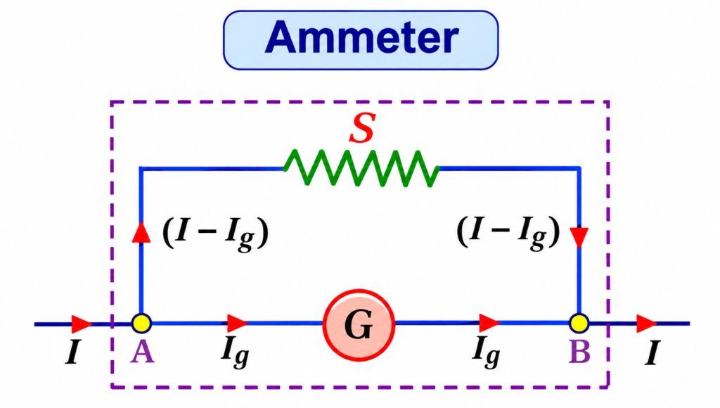
In the circuit:
- G = Resistance of the galvanometer.
- S = Shunt resistance.
- I = Total current entering the parallel combination.
- Ig = Current passing through the galvanometer.
- Is = Current flowing through the shunt.
The total current divides between the two parallel branches.
Therefore,
I = Ig + Is
The parallel arrangement ensures that only a small portion of the total current passes through the galvanometer coil.
Formula for Conversion of Galvanometer into Ammeter
The shunt resistance required to convert a galvanometer into an ammeter is calculated using:
Where:
- S = Shunt resistance in ohms (Ω).
- G = Resistance of the galvanometer in ohms (Ω).
- Ig = Full-scale deflection current of the galvanometer in amperes (A).
- I = Maximum current to be measured by the converted ammeter in amperes (A).
This formula determines the low resistance that must be connected in parallel with the galvanometer to obtain the required current range.
Derivation of Shunt Resistance Formula
Let us derive the expression for shunt resistance when a galvanometer is converted into an ammeter.
Given:
- Resistance of galvanometer = G
- Full-scale deflection current = Ig
- Maximum current to be measured = I
- Shunt resistance = S
Step 1: Calculate the current through the shunt
The total current entering the parallel combination divides into the galvanometer and shunt branches.
According to Kirchhoff’s Current Law:
Therefore, the current through the shunt is:
Step 2: Apply the parallel circuit condition
Since the galvanometer and shunt are connected in parallel, the voltage across both branches is equal.
Therefore,
Using Ohm’s law:
Step 3: Substitute the shunt current
We know that:
Substituting this value:
Step 4: Rearrange the equation
Solving for shunt resistance:
Therefore, the required shunt resistance is:
This is the standard formula used to convert a galvanometer into an ammeter of a specified current range.
Solved Numerical Examples
Let us understand the conversion process with the following numerical problems.
Example 1: Calculate Shunt Resistance
Problem: A galvanometer has an internal resistance of 20 Ω and a full-scale deflection current of 10 mA. Calculate the shunt resistance required to convert it into an ammeter having a range of 5 A.
Given:
- Galvanometer resistance, G = 20 Ω
- Full-scale deflection current, Ig = 10 mA = 0.01 A
- Maximum current, I = 5 A
Using the formula:
Substituting the values:
Therefore,
A shunt resistance of approximately 0.0401 Ω must be connected in parallel with the galvanometer.
Example 2: Calculate the Ammeter Range
Problem: A galvanometer has a resistance of 50 Ω and a full-scale deflection current of 2 mA. It is connected in parallel with a shunt resistance of 0.1 Ω. Determine the maximum current that the converted ammeter can measure.
Given:
- G = 50 Ω
- Ig = 2 mA = 0.002 A
- S = 0.1 Ω
Using the shunt formula:
Rearranging:
Substituting the values:
The converted ammeter can measure a maximum current of 1.002 A.
Example 3: Calculate Galvanometer Current
Problem: A total current of 2 A enters a parallel combination of a galvanometer and shunt. If the galvanometer carries 5 mA, determine the current flowing through the shunt.
Given:
- Total current, I = 2 A
- Galvanometer current, Ig = 5 mA = 0.005 A
Using Kirchhoff’s Current Law:
Therefore,
The current flowing through the shunt is 1.995 A.
Characteristics of a Galvanometer Converted into an Ammeter
After connecting a suitable shunt resistance, the galvanometer behaves as an ammeter with an extended current-measuring range.
Its main characteristics are:
- Low internal resistance: The parallel shunt reduces the overall resistance of the instrument.
- Series connection: The converted ammeter is connected in series with the electrical circuit.
- Extended measuring range: It can measure currents much larger than the original galvanometer full-scale current.
- Current division: Most of the total current flows through the shunt.
- Protection of moving coil: The shunt limits the current passing through the galvanometer.
- Proportional indication: The pointer deflection remains proportional to the total current when the shunt ratio is fixed.
The equivalent resistance of the converted ammeter is:
Where RA is the effective resistance of the ammeter.
Since S is very small compared with G, the effective resistance is also very low.
Why Is Shunt Resistance Very Low?
The shunt resistance must be very small compared with the galvanometer resistance because it is designed to carry most of the circuit current.
A low-resistance shunt provides the following benefits:
- It diverts most of the current away from the sensitive galvanometer coil.
- It produces a small voltage drop across the parallel combination.
- It reduces the effective resistance of the converted ammeter.
- It minimizes the effect of the measuring instrument on the circuit.
For accurate measurements, shunts are commonly manufactured using materials such as manganin because of their relatively low temperature coefficient of resistance.
Advantages of Converting a Galvanometer into an Ammeter
Converting a galvanometer into an ammeter offers several practical advantages:
- It extends the current measurement range of the instrument.
- It protects the sensitive moving coil from excessive current.
- It provides a relatively low-resistance measuring instrument.
- Different current ranges can be obtained by selecting suitable shunt resistances.
- It makes use of the existing galvanometer mechanism.
- It allows measurement of larger currents without directly passing the entire current through the coil.
Limitations and Precautions
Although a shunt protects the galvanometer, the converted ammeter must be designed and connected correctly.
The following points should be considered:
- The shunt must have the correct resistance value.
- Loose connections can introduce measurement errors.
- Excessive current can cause shunt overheating.
- Temperature changes can affect shunt resistance and measurement accuracy.
- The shunt must have an adequate current and power rating.
- The ammeter must always be connected in series with the load.
If the shunt becomes disconnected, the entire circuit current may pass through the galvanometer coil. This can cause severe damage to the instrument.
Conversion of Galvanometer into Ammeter vs Voltmeter
A galvanometer can be converted into either an ammeter or a voltmeter by connecting an additional resistance. However, the resistance value and connection method are different.
| Basis | Galvanometer as Ammeter | Galvanometer as Voltmeter |
| Additional resistance | Low resistance (shunt) | High resistance (multiplier) |
| Connection of resistance | Parallel | Series |
| Instrument connection | Series with load | Parallel across load |
| Effective resistance | Very low | Very high |
| Main purpose | Measures current | Measures voltage |
| Formula | S = IgG/(I − Ig) | Rs = V/Ig − G |
Conclusion
The conversion of a galvanometer into an ammeter is achieved by connecting a low-value shunt resistance in parallel with its moving coil. The shunt carries most of the circuit current, while the galvanometer receives only the small current required for full-scale deflection.
The shunt resistance is calculated using the formula S = IgG/(I − Ig). This arrangement increases the current-measuring capacity of the instrument and reduces its effective resistance. Thus, a sensitive galvanometer can be adapted to measure larger electrical currents safely and accurately.
Read Next: