A Vibration Galvanometer is a sensitive electrical measuring instrument used to detect the presence of alternating current (AC) or alternating electromotive force (EMF). It works on the principle of mechanical resonance, in which the natural frequency of the moving system is adjusted to match the frequency of the alternating current being measured.
When the frequency of the applied AC becomes equal to the natural frequency of the moving element, the instrument produces maximum vibration amplitude. This makes it particularly useful for detecting very small alternating currents and determining the balance point in AC bridge circuits.
Working Principle of Vibration Galvanometer
The working principle of a vibration galvanometer is based on mechanical resonance.
When an alternating current flows through its moving coil, it produces an alternating magnetic field and a corresponding deflecting torque. This torque causes the moving system to oscillate.
The amplitude of oscillation depends on the relationship between the frequency of the applied current and the natural frequency of the moving system.
- When the frequencies are different: The moving element vibrates with a relatively small amplitude.
- When the frequencies are equal: Resonance occurs, producing maximum vibration amplitude.
- When the current is removed: The moving system gradually comes to rest due to damping.
The natural frequency of the moving system can be adjusted by changing the tension of its suspension or the control mechanism.
Construction of Vibration Galvanometer
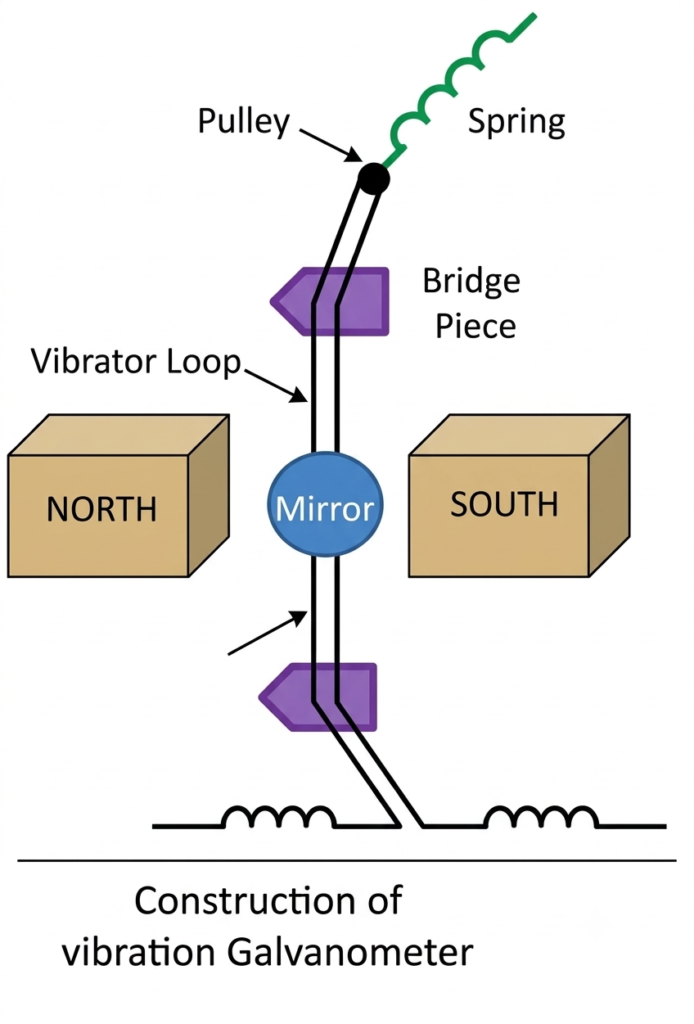
A vibration galvanometer consists of a lightweight moving element suspended in a magnetic field. Its important constructional parts are described below.
1. Moving Element: A small, lightweight coil or moving system is placed in the magnetic field. It responds to the alternating torque produced by the applied current.
2. Suspension Wire: A fine bronze or platinum wire supports the moving system. It also provides the necessary restoring force for oscillation.
3. Pulley and Spring: The upper end of the suspension wire is connected to an adjustable pulley and spring arrangement. This mechanism controls the tension in the suspension.
4. Ivory Bridges: Two ivory bridges support the suspension arrangement. Their positions can be adjusted to change the effective length and tension of the wire.
5. Mirror: A small mirror is attached to the suspension system. It reflects a beam of light onto a graduated scale or screen, allowing small vibrations to be observed.
6. Magnetic System: Permanent magnets or an electromagnet produce the magnetic field required for the operation of the instrument.
7. Adjusting Mechanism: The adjustment arrangement changes the natural frequency of the moving system so that it can match the frequency of the applied AC.
Tuning of Vibration Galvanometer
Tuning is the process of adjusting the natural frequency of a vibration galvanometer to match the frequency of the alternating current being measured.
The tuning is generally achieved by changing the tension of the suspension wire or spring. This changes the restoring force and consequently the natural frequency of the moving system.
When the two frequencies become equal, resonance occurs and the moving element vibrates with maximum amplitude.
The reflected light spot or band on the scale then shows a pronounced movement, indicating the presence of the corresponding AC signal.the attached mirror and an optical arrangement.
Theory and Equation of Vibration Galvanometer
The behaviour of a vibration galvanometer can be explained using the equation of motion of an oscillating system.
Consider an alternating current flowing through the moving coil:
Where:
- = Instantaneous current
- = Maximum value of current
- = Angular frequency of AC
- = Time
The deflecting torque produced by the current is proportional to the instantaneous current.
Therefore,
Substituting the value of current:
Where represents the displacement or torque constant, depending on the instrument’s convention.
The equation of motion of the moving system is:
Substituting the deflecting torque:
Where:
- = Moment of inertia of the moving system
- = Damping coefficient
- = Restoring or control torque constant
- = Angular displacement
- = Torque constant
- = Maximum applied current
- = Angular frequency of applied AC
Natural Frequency of Vibration Galvanometer
The natural angular frequency of the moving system, neglecting damping, is:
The corresponding natural frequency in hertz is:
Where:
- = Natural frequency in hertz
- = Restoring torque constant
- = Moment of inertia
For resonance, the applied frequency must be approximately equal to the natural frequency:
At this condition, the vibration amplitude becomes maximum, provided the damping is sufficiently low.
Effect of damping: Damping influences the amplitude and sharpness of resonance. Lower damping produces a larger and sharper resonance response, whereas higher damping reduces the maximum amplitude.
Types of Vibration Galvanometer
Vibration galvanometers are broadly classified into two types based on the construction of their moving systems:
- Moving Coil Type Vibration Galvanometer
- Moving Magnet Type Vibration Galvanometer
1. Moving Coil Type Vibration Galvanometer
In a moving coil vibration galvanometer, a lightweight coil is suspended in the magnetic field produced by permanent magnets or an electromagnet.
When alternating current passes through the coil, it interacts with the magnetic field and produces an alternating deflecting torque. Consequently, the coil starts vibrating at the frequency of the applied current.
The suspension arrangement allows the coil to oscillate freely. Its natural frequency is adjusted to match the frequency of the AC supply to obtain maximum vibration amplitude.
This type of instrument is suitable for detecting small alternating currents and is commonly associated with AC bridge measurement techniques.
2. Moving Magnet Type Vibration Galvanometer
In a moving magnet vibration galvanometer, a small permanent magnet forms the moving element and is suspended between the poles of a magnetic system. A coil is placed around or near the magnet to produce the required magnetic field.
When alternating current flows through the coil, it generates an alternating magnetic field. This field interacts with the suspended permanent magnet and produces an alternating torque, causing the magnet to oscillate.
A small mirror may be attached to the suspended magnet to observe its vibrations using a reflected beam of light.
The natural frequency of the moving magnet is adjusted by changing the suspension tension or the magnetic arrangement. When the natural frequency matches the frequency of the applied alternating current, resonance occurs and the magnet vibrates with maximum amplitude.
This type of vibration galvanometer is also used for detecting small alternating currents and identifying balance conditions in AC electrical measurement circuits.
Applications of Vibration Galvanometer
Vibration galvanometers are mainly used in electrical measurement systems where the detection of small alternating currents or voltages is required.
Important applications include:
1. AC Bridge Circuits: Used as a null detector to identify the balance condition in alternating-current bridge circuits.
2. Detection of Small AC Signals: Helps detect very low alternating currents that cannot be easily identified using ordinary indicating instruments.
3. Frequency Measurement: Can be used in frequency comparison arrangements by adjusting the natural frequency until resonance occurs.
4. Measurement of Unknown Inductance: Used in AC bridge methods for determining unknown inductance.
5. Measurement of Capacitance: Helps detect the balance condition in AC bridges used for capacitance measurement.
6. Electrical Laboratory Experiments: Used in practical experiments involving resonance, AC circuits and electrical measurement techniques.
Conclusion
A vibration galvanometer is a sensitive instrument that detects alternating currents and EMFs using the principle of mechanical resonance. Its moving system oscillates when an alternating torque acts on it, and the vibration amplitude becomes maximum when the natural frequency matches the applied frequency. It is particularly useful as a null detector in AC bridge circuits for measuring unknown electrical quantities such as inductance and capacitance.
Read Next:
- Conversion of Galvanometer into Voltmeter: Formula, Derivation and Working
- Conversion of Galvanometer into Ammeter – Formula, Circuit Diagram and Derivation
- Applications of Galvanometer
- Galvanometer: Definition, Working Principle, Construction and Working
- Sensitivity of Galvanometer: Formula, Types, Factors and Explanation
- Figure of Merit of a Galvanometer: Formula, Experiment and Calculation
- Galvanometer Resistance: Formula, Calculation and Measurement
- Tangent Galvanometer: Diagram, Principle, Formula, Working and Experiment
- Types of Galvanometer: Classification and Types Explained
- D’Arsonval Galvanometer: Working Principle, Construction, Diagram and Applications
- Ballistic Galvanometer: Definition, Construction, Working Principle, Diagram, Theory, Equation, and Calibration
- Mirror Galvanometer: Definition, Construction, Working Principle, Uses and Advantages