Learn about LT Panel (Low Tension Panel), its types, design, components, maintenance, and applications in power distribution systems for industrial and commercial use.
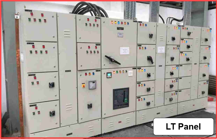
What is the LT(Low Tension) Panel?
The LT (Low Tension) Panel serves as a power control center, receiving and distributing a 415V power supply. It receives power from one or two sources: for example- the transformer’s 433V outgoing supply and the DG synchronization panel’s output. The LT panel efficiently distributes power to various electrical devices, distribution boards, and feeders, ensuring safe operation with protective devices.
LT Panel Full Form
Full form of LT Panel is Low Tension Panel. It is an electrical distribution board that receives 415V supply from a transformer or generator and distributes it to various electrical loads. It is commonly used in industrial, commercial, and residential buildings for power distribution, control, and protection.
LT Panel Circuit and Single Line Diagram
The LT (Low Tension) Panel is a crucial component in an electrical distribution system, responsible for receiving and distributing a 415V power supply. It acts as a power control center, ensuring efficient power management and protection for various electrical loads.
In the given connection diagram, the LT panel receives power from two main sources:
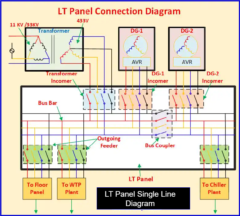
- Transformer Supply: The primary power source is a transformer that steps down high voltage to 433V and feeds the LT panel.
- DG (Diesel Generator) Backup: The LT panel is also connected to two DG sets, which act as backup power sources during grid failure. A DG synchronization panel ensures seamless switching between the mains and generator supply.
Once the LT panel receives power, it distributes it to various outgoing feeders based on the load requirements. Some of the key outgoing feeders include:
- Floor Panel: Supplies power to various floors of the building or facility.
- Water Treatment Plant (WTP): Provides power for water purification and treatment systems.
- Chiller Plant: Supplies power to HVAC systems for cooling and air conditioning.
Components of LT Panel
1. Measuring Meters
Measuring meters are essential for monitoring and analyzing various electrical parameters in a system. They help in measuring voltage, current, power, energy consumption, and other critical values. The most commonly used measuring meters include:
A. Digital Multifunction Meter
A digital multifunction meter is a versatile device used to measure multiple electrical parameters, including:
- Current (Amps)
- Voltage (Volts)
- Power (Watts)
- Energy Consumption (kWh)
- Power Factor
These meters provide real-time data, improving accuracy and efficiency in power monitoring.
B. Energy Meter
Energy meters are used to measure power consumption in an electrical system. Different types of energy meters include:
- Three-Phase Dual Source Energy Meter: Measures energy from two power sources, such as grid and generator supply.
- Three-Phase Energy Meter: Monitors energy usage in three-phase electrical systems.
C. Analog Ammeter and Voltmeter
Analog ammeters and voltmeters operate on electromagnetic principles and are commonly used for basic voltage and current measurements. While digital meters provide higher accuracy, analog meters are still used in some applications due to their simplicity and reliability.
2. Indicator and Selector Switches
Indicator lights and selector switches play a crucial role in monitoring and controlling electrical panel operations. They help in identifying system status and switching between different operational modes.
A. Indicators
Indicators are used to display the status of various panel operations. Different types of indicators come in various colors, each representing specific system conditions. These include:
- Phase Indicators:
- R Phase (Red)
- Y Phase (Yellow)
- B Phase (Blue)
- Circuit Breaker Status Indicators:
- ACB ON (Air Circuit Breaker On) – Green
- ACB OFF (Air Circuit Breaker Off) – Red
- ACB Trip (Fault Condition) – Amber
- MCCB ON (Molded Case Circuit Breaker On) – Green
- MCCB OFF (Molded Case Circuit Breaker Off) – Red
- MCCB Trip (Fault Condition) – Amber
These indicators enhance safety by providing a clear visual representation of power and breaker statuses.
B. Selector Switches
Selector switches are used to control the operational mode of the panel, allowing manual or automatic operation. Common types include:
- Auto/Manual Selector Switch: Used to switch between automatic and manual control of equipment.
- Source Selection Switch: Helps in selecting power sources, such as DG supply or mains power.
- Changeover Switch: Used to transfer power supply between two sources, ensuring continuity.
These switches improve operational flexibility and ensure seamless power management.
3. Protection Relays
Protection relays are automatic switching devices that detect abnormalities in an electrical circuit and send a tripping signal to the circuit breaker to isolate faulty components. This prevents damage to equipment and ensures system safety.
In an LT panel, different types of protection relays are installed for various safety measures. These include:
- Differential Relay
- Over Voltage Relay (OVR)
- Under Voltage Relay (UVR)
- Earth Fault Relay (EFR)
- Reverse Power Relay (RPR)
Each of these relays plays a critical role in protecting electrical systems from faults and ensuring uninterrupted operation.
A. Differential Relay
A differential relay is widely used in generator and transformer panels for protecting against power discrepancies between input and output.
Working Principle:
- It continuously monitors the current at both input and output sides.
- If the current difference exceeds the set limit, the relay activates and trips the circuit breaker.
- This ensures protection against internal faults, preventing severe damage to equipment.
B. Over Voltage Relay (OVR)
An over-voltage relay detects high voltage levels beyond the permissible range and prevents insulation failure.
Working Principle:
- If the supply voltage exceeds the preset limit (usually 5% above 415V), the relay sends a trip signal to the circuit breaker.
- Used in LT panels, isolation panels, and transformer output circuits for system safety.
C. Under Voltage Relay (UVR)
An under-voltage relay protects electrical equipment from low-voltage conditions that may cause excessive current draw and overheating.
Working Principle:
- If voltage drops below the set value, the relay triggers a trip command.
- This prevents overloading of motors and other connected equipment.
- Used in LT panels and transformer circuits.
D. Earth Fault Relay (EFR)
An earth fault relay detects leakage currents and prevents hazards due to insulation failure.
Working Principle:
- It continuously monitors leakage current in the system.
- If leakage current exceeds 20-50% of the equipment’s rated current, the relay trips the breaker.
- Used in LT panels, HT panels, and other critical electrical panels.
E. Reverse Power Relay (RPR)
A reverse power relay prevents power from flowing in the opposite direction, especially in generator (DG) panels.
Working Principle:
- It ensures that the power from the DG set does not flow back into the grid when the main power supply is restored.
- Prevents back-feed, which can cause serious damage to generators and power networks.
- Commonly used in DG incomer panels for system protection.
F. Overcurrent Relay (OCR)
An overcurrent relay protects electrical circuits from excessive current flow.
Working Principle:
- Detects current above the rated capacity.
- Sends a trip signal to the breaker to prevent overheating and damage.
- Used in feeder panels, motor control centers, and transformers.
G. Thermal Overload Relay (TOR)
A thermal overload relay protects motors from overheating due to prolonged overcurrent conditions.
Working Principle:
- Measures temperature rise in motor windings.
- Trips the breaker if temperature exceeds safe limits.
- Commonly used in motor control circuits and LT panels.
H. Phase Sequence Relay (PSR)
A phase sequence relay ensures that the three-phase supply follows the correct phase order.
Working Principle:
- Detects incorrect phase sequencing.
- Trips the breaker if the sequence is reversed to prevent motor damage.
- Used in motor control circuits and industrial LT panels.
Protection relays are an essential part of LT panels, ensuring system safety, reliability, and uninterrupted operation. By detecting faults and triggering timely circuit breaker actions, they safeguard electrical networks from damage due to overvoltage, undervoltage, earth faults, and power reversals.
4. Circuit Breakers
A circuit breaker is a crucial protective device used in LT panels to control and safeguard power supply lines. It enables the switching of power between incomers and outgoing feeders while providing protection against overcurrent, short circuits, and other electrical faults.
A. Air Circuit Breaker (ACB):
An Air Circuit Breaker (ACB) is a protective switching device used in LT panels to manually or automatically control the power supply. It plays a crucial role in safeguarding the electrical system from overload, short circuits, and other faults. ACBs use air as the arc-quenching medium, which effectively extinguishes electrical arcs during switching operations. They are commonly used in high-capacity power distribution systems for industrial and commercial applications.
B. Molded Case Circuit Breaker (MCCB):
A Molded Case Circuit Breaker (MCCB) is a compact and efficient circuit breaker designed for switching and protecting electrical circuits in LT panels. It provides protection against overload and short circuits and is typically used for current ratings ranging from 100A to 800A. MCCBs are installed in LT panels to control power distribution to various outgoing feeders, ensuring a safe and reliable electrical network.
C. Miniature Circuit Breaker (MCB):
A Miniature Circuit Breaker (MCB) is a small, automatic circuit breaker designed for low-current applications in LT panels. It provides protection against overload and short circuits in lighting circuits, small motors, and control panels. MCBs are commonly used in residential, commercial, and industrial power distribution systems, with current ratings typically up to 125A.
D. Residual Current Circuit Breaker (RCCB):
A Residual Current Circuit Breaker (RCCB) is a protective device used in LT panels to detect leakage currents and prevent electrical shocks and fire hazards. It operates by sensing any imbalance in the current flow between the live and neutral conductors. If leakage exceeds a preset threshold, the RCCB immediately disconnects the circuit, ensuring the safety of both people and equipment. RCCBs are commonly rated between 30mA to 300mA sensitivity.
LT Panel Maintenance Procedure
Maintaining an LT (Low Tension) panel is essential for ensuring its safe operation, reliability, and efficiency. A well-maintained LT panel reduces the risk of electrical faults, breakdowns, and power failures. Below is a step-by-step procedure for LT panel maintenance:
1. Visual Inspection
- Check for dust, dirt, moisture, or corrosion on the panel surface and components.
- Inspect cable connections, busbars, and insulation for any damage or overheating signs.
- Ensure all labels and indicators are visible and intact.
2. Cleaning and Tightening
- Switch off the panel and confirm no live voltage using a voltmeter.
- Clean the external and internal surfaces using a dry cloth or vacuum cleaner.
- Tighten all loose connections of busbars, cables, and terminals to prevent overheating.
3. Functional Testing
- Check the operation of measuring meters, indicator lamps, and selector switches.
- Test the circuit breakers (ACB, MCCB, MCB, RCCB) for proper switching and tripping.
- Verify that protection relays (overvoltage, earth fault, differential, reverse power) function correctly.
4. Insulation and Earthing Checks
- Measure insulation resistance using a Megger to ensure proper insulation levels.
- Check the earthing connection for continuity and tightness.
5. Load and Voltage Testing
- Monitor voltage, current, and power factor under normal load conditions.
- Ensure balanced load distribution to avoid overloading.
6. Record and Report
- Maintain a logbook of maintenance activities and test results.
- Report any faulty components or abnormalities for immediate action.
Regular maintenance ensures safe and efficient operation, extending the life of the LT panel and preventing unexpected failures.
Types of LT Panels
LT (Low Tension) Panels are categorized based on their function, application, and configuration. The main types of LT panels are:
- Power Control Center (PCC Panel)
- Used for power distribution in industrial and commercial setups.
- Controls the main power supply from a transformer or generator.
- Motor Control Center (MCC Panel)
- Designed to control and protect multiple motors in an industrial setup.
- Includes circuit breakers, relays, and starters for motor operation.
- Automatic Power Factor Correction (APFC Panel)
- Maintains the power factor of the system using capacitor banks.
- Reduces energy consumption and avoids power factor penalties.
- Distribution Panel
- Distributes power to various feeders in a building or industrial plant.
- Ensures proper power supply to different loads.
- DG Synchronization Panel
- Synchronizes multiple Diesel Generators (DGs) for efficient load sharing.
- Ensures uninterrupted power supply in case of grid failure.
- Changeover Panel (ATS/AMF Panel)
- ATS (Automatic Transfer Switch) Panel: Automatically switches power between grid and generator.
- AMF (Auto Mains Failure) Panel: Automatically starts the generator during a power failure.
- Capacitor Panel
- Used to improve power factor and maintain voltage stability.
- Contains capacitor banks and relays for automatic switching.
- Lighting Distribution Panel
- Used for lighting circuit distribution in commercial buildings, factories, and public places.
Each type of LT panel plays a crucial role in managing and protecting electrical systems in different applications.
LT Panel Design
The design of an LT (Low Tension) Panel is crucial for ensuring efficient power distribution, safety, and reliability in electrical systems. LT panels are designed based on power requirements, load distribution, protection, and control features.
1. Understanding Power Requirements
- The first step in LT panel design is determining the total load demand (in kW or kVA).
- Based on this, the rated capacity of the panel is decided.
- The input voltage level (typically 415V, 3-phase) and the expected current flow are considered.
2. Selection of Components
- Main Circuit Breaker (ACB/MCCB): Protects the system from overcurrent and short circuits.
- Busbars: Copper or aluminum busbars are used for carrying high currents safely.
- Switching Devices: Includes contactors, relays, and isolators for control and protection.
- Metering Devices: Digital meters, energy meters, and multifunction meters for monitoring power parameters.
- Protection Relays: Overvoltage, undervoltage, earth fault, and differential relays ensure system safety.
- Capacitor Banks: Used in APFC panels to improve power factor.
3. Panel Layout and Enclosure Design
- The enclosure should be IP-rated (IP54/IP65) for protection against dust and moisture.
- Ventilation systems (fans and louvers) are included to prevent overheating.
- Cable entry and termination points are designed for easy installation and maintenance.
4. Safety Considerations
- Proper earthing and grounding to prevent electrical shocks.
- Short-circuit withstand capacity of components must be adequate.
- Fire-resistant material is used for insulation and wiring.
A well-designed LT panel ensures efficient power distribution, system safety, and long-term reliability in industrial and commercial applications.
Read Next: