A ballistic galvanometer is a sensitive electrical measuring instrument used to measure the quantity of electric charge passing through a circuit during a short time interval. Unlike an ordinary galvanometer, which measures current, a ballistic galvanometer determines the total charge transferred through its coil.
It works on the principle that the initial angular deflection of its moving coil is proportional to the total electric charge passing through it, provided the charge passes in a sufficiently short time compared with the natural period of oscillation of the coil.
A ballistic galvanometer is commonly used in electrical experiments involving capacitors, electromagnetic induction, magnetic flux measurement and mutual inductance.
What Is a Ballistic Galvanometer?
A ballistic galvanometer is a modified moving-coil galvanometer designed to measure a brief flow of electric charge rather than a continuously flowing current.
When a short-duration current passes through its coil, the coil receives an angular impulse and begins to rotate. The initial deflection, known as the first throw, depends on the total charge that has passed through the coil.
The instrument is designed with a large moment of inertia and a relatively long time period. These characteristics allow the coil to respond to the total charge transferred during a short electrical event.
Important distinction:
- An ordinary galvanometer measures small electric current.
- A ballistic galvanometer measures the total electric charge transferred during a short interval.
The SI unit of charge measured by a ballistic galvanometer is the coulomb (C).
Digarm of Ballistic Galvanometer
The diagram of ballastic galvanometer is shown in the image below.
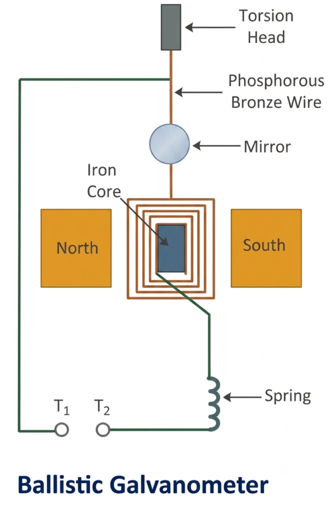
Construction of Ballistic Galvanometer
A ballistic galvanometer has a construction similar to a moving-coil galvanometer, but its moving system is specially designed to measure short-duration electrical impulses.
Its main components are explained below.
1. Moving Coil
The moving coil consists of several turns of insulated copper wire wound around a lightweight, non-conducting frame.
The coil is suspended between the pole pieces of a permanent magnet. When an electric charge passes through the coil, the magnetic field produces a torque that causes it to rotate.
2. Permanent Magnet
A strong permanent magnet provides the magnetic field required for the operation of the instrument.
The pole pieces are shaped to produce a radial magnetic field. This arrangement ensures that the deflecting torque remains proportional to the current flowing through the coil.
3. Soft Iron Core
A cylindrical soft iron core is placed inside the moving coil.
It serves two main purposes:
- Concentrates the magnetic flux through the coil.
- Produces a strong radial magnetic field in the air gap.
This improves the sensitivity of the instrument.
4. Suspension System
The coil is suspended using a thin phosphor-bronze strip or filament.
The suspension supports the moving coil and provides the electrical connection to it. Its torsional elasticity also produces the controlling torque that opposes the coil’s rotation.
5. Lower Spring
A flexible spring is connected to the lower part of the coil.
It completes the electrical circuit and provides the restoring torque required to bring the coil back towards its original position.
6. Damping Arrangement
A ballistic galvanometer is designed with very low damping so that the coil can undergo relatively large oscillations after receiving an electrical impulse.
Excessive damping would reduce the first throw and affect the measurement of charge. Therefore, the damping is kept low and its effect is considered during accurate measurements.
7. Pointer and Scale
A pointer or mirror arrangement indicates the angular displacement of the moving coil.
The first maximum deflection is observed on a calibrated scale. This reading is used to calculate the total charge passing through the instrument.
Working Principle of Ballistic Galvanometer
The working principle of a ballistic galvanometer is based on the relationship between the total electric charge passing through its coil and the angular deflection produced by that charge.
When a short-duration current flows through the moving coil, the magnetic field produces a deflecting torque. This torque gives the coil an angular impulse, causing it to move from its initial position.
Since the current flows for a very short time, the coil does not have sufficient time to move significantly while the charge is passing through it. Therefore, the total angular impulse depends on the total charge transferred rather than the instantaneous current.
After the current stops flowing, the coil continues to rotate due to the angular momentum it has acquired. It reaches a maximum angular displacement before the suspension’s restoring torque brings it back.
This maximum displacement is called the first throw of the ballistic galvanometer.
The first throw is proportional to the total charge passing through the coil.
Where:
- Total electric charge (C)
- = First angular deflection (radians)
Ballistic Galvanometer Equation
Where is the torsional constant, is the time period, and is the first throw.
For a given galvanometer, all the quantities except \(q\) and \(\theta\) remain constant.
Therefore,
Where,
Here, is called the ballistic galvanometer constant or charge constant.
It represents the quantity of charge required to produce one unit of angular deflection.
Important: The derivation assumes that the charge passes through the coil in a time much shorter than its natural period
Theory and Derivation of Ballistic Galvanometer
Consider a rectangular coil having \(N\) turns placed in a uniform radial magnetic field.
Let:
- = Number of turns in the coil
- = Magnetic flux density (T)
- = Length of the coil (m)
- = Breadth of the coil (m)
- = Area of the coil (m²)
- = Current flowing through the coil (A)
- = Total charge passing through the coil (C)
- = Moment of inertia of the moving coil (kg·m²)
- = Torsional constant of the suspension (N·m/rad)
- = First angular deflection (rad)
Step 1: Area of the Rectangular Coil
The area of a rectangular coil is the product of its length and breadth.
Step 2: Deflecting Torque
When current flows through the coil placed in a magnetic field, a deflecting torque acts on it.
The deflecting torque is given by:
Substituting the area of the coil:
Step 3: Angular Impulse Produced by the Coil
The angular impulse acting on the coil is equal to the time integral of the deflecting torque.
Since , , and are constant:
The total electric charge passing through the coil is:
Therefore,
Step 4: Angular Momentum of the Coil
According to the impulse-momentum principle, angular impulse is equal to the change in angular momentum.
Initially, the coil is at rest. Therefore, its initial angular momentum is zero.
If is the angular velocity acquired by the coil immediately after the charge passes through it, its angular momentum is:
Equating angular impulse and angular momentum:
Therefore,
Step 5: Kinetic Energy of the Moving Coil
After receiving the angular impulse, the coil moves with angular velocity \(\omega\).
Its kinetic energy is:
As the coil reaches its maximum angular deflection, its angular velocity becomes zero.
At this point, the kinetic energy is converted into the potential energy stored in the twisted suspension.
The potential energy is:
Applying the conservation of energy:
Simplifying:
Taking the square root:
Step 6: Derivation of Ballistic Galvanometer Equation
Substituting the value of angular velocity from equation (2) into equation (1):
Simplifying:
Therefore, the charge passing through the ballistic galvanometer is:
This is the fundamental equation of a ballistic galvanometer.
Step 7: Expression in Terms of Time Period
The time period of oscillation of the moving coil is:
Rearranging:
Thus,
Substituting this value into the charge equation:
Hence, the final equation becomes:
Calibration of Ballistic Galvanometer
Calibration is the process of determining the ballistic galvanometer constant experimentally.
Once the constant is known, the instrument can be used to calculate an unknown quantity of electric charge from the observed first throw.
Two commonly used calibration methods are:
- Calibration using a capacitor.
- Calibration using mutual inductance.
1. Calibration Using a Capacitor
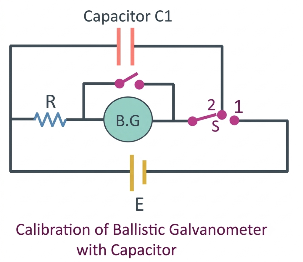
In this method, a capacitor of known capacitance is charged to a known voltage and then discharged through the ballistic galvanometer.
The circuit consists of:
- A capacitor of known capacitance.
- A DC voltage source .
- A two-way switch.
- A suitable resistance.
- A ballistic galvanometer.
Working procedure:
- First, the switch is connected to the charging position so that the capacitor becomes fully charged by the voltage source.
- The switch is then moved to the discharging position, connecting the charged capacitor to the ballistic galvanometer.
- The capacitor discharges through the galvanometer and sends a short-duration current through its coil.
- The moving coil receives an angular impulse and produces a first throw of .
- The observed deflection is used to calculate the ballistic galvanometer constant.
The charge stored in the capacitor before discharge is:
Since the capacitor discharges through the galvanometer, the charge passing through its coil is:
The ballistic galvanometer constant is:
Therefore,
This method determines the charge constant using known capacitance and voltage values.
2. Calibration Using Mutual Inductance
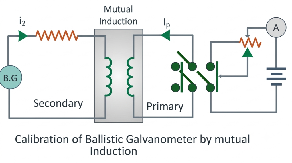
This method uses the principle of electromagnetic induction to determine the ballistic galvanometer constant.
The experimental arrangement consists of two coils:
- Primary coil: Connected to a DC supply, key and rheostat to control the current.
- Secondary coil: Connected to the ballistic galvanometer.
The two coils are placed close to each other so that magnetic flux produced by the primary coil links with the secondary coil.
Working procedure:
- A known current is established in the primary coil.
- The magnetic field produced by the primary coil links with the secondary coil.
- When the primary current is suddenly changed or interrupted, the magnetic flux linking the secondary coil changes.
- Due to mutual induction, an electromotive force is induced in the secondary coil.
- The induced EMF produces a momentary current through the ballistic galvanometer.
- The galvanometer shows a first throw, which is used to determine its constant.
According to Faraday’s law of electromagnetic induction:
Where:
- = Induced EMF in the secondary coil (V)
- = Mutual inductance between the coils (H)
- = Primary current (A)
The total charge passing through the secondary circuit is:
Taking the magnitude:
Where is the total resistance of the secondary circuit and is the change in primary current.
If the primary current is reduced from to zero:
Therefore,
Since the ballistic galvanometer constant is:
We get:
This expression determines the ballistic galvanometer constant using known mutual inductance, primary current and secondary circuit resistance.
Note: The formula assumes that the entire induced charge flows through the galvanometer and that the total secondary circuit resistance is known.
Characteristics of Ballistic Galvanometer
A ballistic galvanometer has certain characteristics that distinguish it from an ordinary moving-coil galvanometer.
1. Large moment of inertia: The moving coil has a large moment of inertia, which increases its natural time period and allows it to respond to short-duration current impulses.
2. Long time period: The coil takes relatively more time to complete one oscillation. This ensures that the charge passes through the coil before significant mechanical movement occurs.
3. Low damping: The damping is kept low to minimize energy loss and reduce the difference between the actual and observed first throw.
4. High charge sensitivity: The instrument is designed to detect small quantities of electric charge.
5. Short-duration current measurement: It measures the total charge transferred during a brief electrical event rather than the instantaneous current.
Advantages of Ballistic Galvanometer
The important advantages include:
- It measures small quantities of electric charge accurately.
- It is suitable for measuring charge transferred in a short time.
- It can be used in electromagnetic induction experiments.
- It helps determine mutual inductance between two coils.
- It can be used to calculate magnetic flux changes.
- It provides a simple experimental method for studying capacitor discharge.
Disadvantages of Ballistic Galvanometer
Some limitations of the instrument are:
- It cannot directly measure continuous current like an ordinary ammeter.
- Its moving system is delicate and requires careful handling.
- Low damping can result in prolonged oscillations.
- The first throw can be affected by damping and mechanical friction.
- Accurate measurements require proper calibration.
- The charge must pass through the coil in a time much shorter than the natural period of oscillation.
Applications of Ballistic Galvanometer
Ballistic galvanometers are mainly used in electrical laboratories and experiments involving the transfer of electric charge.
Some important applications are:
- Measurement of electric charge: Used to determine the quantity of charge passing through a circuit during a short interval.
- Magnetic flux measurement: Used to determine changes in magnetic flux linked with a coil.
- Mutual inductance measurement: Used to calculate mutual inductance between two electrical coils.
- Capacitor experiments: Used to measure the charge released during capacitor discharge.
- Electromagnetic induction: Used to study the induced charge produced by changing magnetic fields.
- Magnetic field experiments: Used in laboratory investigations involving changes in magnetic flux.
Difference Between Ordinary Galvanometer and Ballistic Galvanometer
| Basis | Ordinary Galvanometer | Ballistic Galvanometer |
| Main purpose | Measures small electric current | Measures quantity of electric charge |
| Principle | Deflection depends on current | First throw depends on total charge |
| Moment of inertia | Comparatively small | Comparatively large |
| Time period | Comparatively short | Comparatively long |
| Damping | Generally higher | Kept low |
| Deflection | Indicates current magnitude | First throw indicates charge |
| Applications | Current detection and measurement | Charge and magnetic flux measurement |
Conclusion
A ballistic galvanometer is a specialized moving-coil instrument used to measure the quantity of electric charge passing through a circuit during a short time interval. Its operation is based on the angular impulse produced when a momentary current flows through the coil.
The first throw of the moving coil is proportional to the total charge transferred. Its large moment of inertia, long time period and low damping make it suitable for detecting short electrical impulses.
The instrument can be calibrated using a known capacitor or mutual inductance arrangement. It is particularly useful in experiments involving capacitor discharge, electromagnetic induction, magnetic flux and mutual inductance.
Read Next:
- Conversion of Galvanometer into Voltmeter: Formula, Derivation and Working
- Conversion of Galvanometer into Ammeter – Formula, Circuit Diagram and Derivation
- Applications of Galvanometer
- Galvanometer: Definition, Working Principle, Construction and Working
- Sensitivity of Galvanometer: Formula, Types, Factors and Explanation
- Figure of Merit of a Galvanometer: Formula, Experiment and Calculation
- Galvanometer Resistance: Formula, Calculation and Measurement
- Tangent Galvanometer: Diagram, Principle, Formula, Working and Experiment
- Types of Galvanometer: Classification and Types Explained
- D’Arsonval Galvanometer: Working Principle, Construction, Diagram and Applications