The types of voltmeter are classified according to their operating principle, construction, and method of displaying the measured voltage. Different types are designed to measure AC voltage, DC voltage, or both, depending on their measuring mechanism.
Based on their construction and working principle, the commonly used types of voltmeters are:
- Permanent Magnet Moving Coil (PMMC) Voltmeter
- Moving Iron (MI) Voltmeter
- Electrodynamometer-Type Voltmeter
- Rectifier-Type Voltmeter
- Induction-Type Voltmeter
- Electrostatic Voltmeter
- Digital Voltmeter (DVM)
Voltmeters can also be classified according to the type of voltage they measure:
- DC Voltmeter
- AC Voltmeter
Each type has a different operating principle, measuring range, accuracy, and application. Let’s discuss these types of voltmeters in detail.
Classification or Types of Voltmeter Based on Measuring Principle
The following sections explain the construction and working principles of different types of voltmeter.
1. Permanent Magnet Moving Coil (PMMC) Voltmeter
A Permanent Magnet Moving Coil (PMMC) voltmeter is an electrical measuring instrument used to measure DC voltage.
Working Principle of PMMC Voltmeter
It works on the principle that a current-carrying conductor placed in a magnetic field experiences a mechanical force.
The instrument consists of a lightweight moving coil positioned between the poles of a permanent magnet. When DC voltage is applied, a small current flows through the coil and produces a magnetic field. The interaction between the magnetic field of the coil and the permanent magnet generates a deflecting torque, causing the coil and attached pointer to move over the calibrated scale.
A high-value resistance, called a multiplier, is connected in series with the moving coil. It limits the current and extends the voltage-measuring range of the instrument.
Torque Equation of PMMC Instrument
The deflecting torque produced in a PMMC instrument is given by:
Where:
- = Deflecting torque (N·m)
- = Number of turns in the moving coil
- = Magnetic flux density (Wb/m²)
- = Area of the moving coil (m²)
- = Current flowing through the coil (A)
Since the total resistance of the voltmeter remains constant, the current flowing through the moving coil is proportional to the applied voltage. Therefore, the pointer deflection is directly proportional to the measured DC voltage.
Advantages of PMMC Voltmeter:
- High measurement accuracy and sensitivity.
- Uniform and linear scale.
- Low power consumption.
- Good damping characteristics.
- Suitable for precise DC voltage measurement.
Limitations of PMMC Voltmeter:
- Cannot directly measure AC voltage.
- Sensitive to incorrect polarity.
- Moving components may experience mechanical wear.
- Generally more expensive than moving iron instruments.
A conventional PMMC voltmeter measures DC voltage only. AC voltage can also be measured by using an external or built-in rectifier that converts AC into unidirectional current before applying it to the moving coil.
Applications: PMMC voltmeters are commonly used in DC power supply testing, battery voltage measurement, electronic laboratories, and precision electrical measuring instruments.
Extension of Range in a PMMC Voltmeter
The voltage-measuring range of a Permanent Magnet Moving Coil (PMMC) voltmeter can be increased by connecting a high-value resistance in series with the meter movement. This external resistance is called a multiplier resistance.
The multiplier resistance limits the current flowing through the moving coil when a higher voltage is applied. It protects the sensitive meter movement from excessive current and allows the instrument to measure voltages beyond its original range.
The required multiplier resistance depends on the desired full-scale voltage, the internal resistance of the meter movement, and its full-scale deflection current.
Formula for Multiplier Resistance
The total applied voltage is equal to the sum of the voltage drops across the meter movement and the series multiplier resistance.
Rearranging the equation:
Where:
- = Required full-scale voltage range of the voltmeter (V).
- = Internal resistance of the PMMC meter movement (Ω).
- = External series multiplier resistance (Ω).
- = Full-scale deflection current of the meter movement (A).
The multiplier resistance must also have an appropriate power rating and voltage rating to withstand the electrical stress during measurement.
2. Moving Iron (MI) Voltmeter
A Moving Iron (MI) voltmeter is an electrical measuring instrument used to measure both AC and DC voltage. It works on the principle of magnetic attraction or repulsion produced by a current-carrying coil and a magnetized soft-iron element.
When voltage is applied across the instrument, current flows through its fixed coil and produces a magnetic field. This magnetic field magnetizes the moving iron element, generating a deflecting torque that moves the attached pointer over the calibrated scale.
Working Principle and Torque Equation
The deflecting torque of a moving iron instrument is expressed as:
Where:
- = Deflecting torque (N·m)
- = Current flowing through the coil (A)
- = Inductance of the coil (H)
- = Angular deflection of the moving system
The torque depends on the square of the current. Therefore, its direction remains unchanged even when the current reverses.
For a voltmeter with constant impedance, the average deflecting torque depends on the square of the applied voltage. This allows an MI voltmeter to measure both DC voltage and the RMS value of AC voltage within its specified operating conditions.
Types of Moving Iron Voltmeter
Moving iron instruments are classified into two main types:
- Attraction-Type MI Instrument: Current flowing through the fixed coil produces a magnetic field that attracts a movable soft-iron vane toward the region of stronger magnetic field. This movement produces pointer deflection.
- Repulsion-Type MI Instrument: The current-carrying coil magnetizes two soft-iron vanes with the same polarity. The resulting magnetic repulsion moves the movable vane and attached pointer across the scale.
Advantages of MI Voltmeter:
- Suitable for both AC and DC voltage measurement.
- Simple and rugged construction.
- Economical compared with many precision instruments.
- Can withstand comparatively rough industrial operating conditions.
Limitations of MI Voltmeter:
- Non-uniform scale, particularly near the lower end.
- Higher power consumption than PMMC instruments.
- Measurement errors due to magnetic hysteresis.
- Accuracy can be affected by frequency, waveform, temperature, and external magnetic fields.
MI voltmeters are widely used in AC electrical distribution panels, switchboards, industrial control panels, and general-purpose voltage measurement applications.
3. Electrodynamometer-Type Voltmeter
An electrodynamometer-type voltmeter is an electrical measuring instrument used to measure both AC and DC voltage. It operates on the principle of interaction between the magnetic fields produced by fixed and moving current-carrying coils.
Unlike moving iron instruments, an electrodynamometer instrument uses air-cored coils and does not depend on an iron magnetic circuit. This makes it suitable for precision measurements and AC-DC comparison.
Working Principle of Electrodynamometer-Type Voltmeter
The instrument consists of two fixed coils and a movable coil mounted between them. The fixed and moving coils are connected in series, so the same current flows through both coils.
When voltage is applied, current produces magnetic fields around the coils. The interaction between these fields generates a deflecting torque, causing the moving coil and attached pointer to rotate over the calibrated scale.
The deflecting torque is expressed as:
Where:
- = Deflecting torque (N·m)
- = Current flowing through the coils (A)
- = Mutual inductance between the fixed and moving coils (H)
- = Angular deflection of the moving coil
Since both coils carry the same current, reversing the applied voltage reverses the current in both coils. The direction of the deflecting torque therefore remains unchanged.
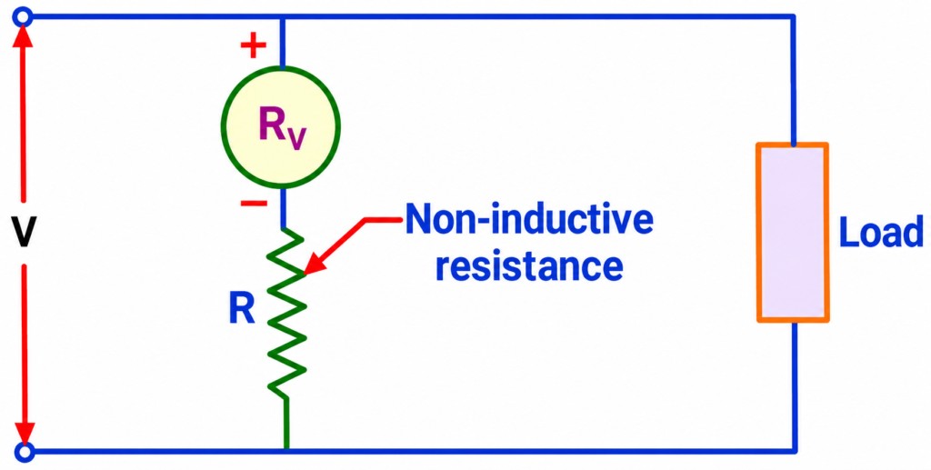
For voltage measurement, a high-value non-inductive resistance is connected in series with the coil circuit. This resistance limits the current and extends the voltage range. The complete instrument is connected in parallel across the points where voltage is to be measured.
For AC measurements, the instrument indicates an effective value under its specified operating conditions. Its accuracy can be affected by frequency-dependent impedance and phase differences between the current and voltage.
Advantages of Electrodynamometer-Type Voltmeter:
- Suitable for both AC and DC measurements.
- Does not suffer from iron hysteresis errors.
- Can be used as an AC-DC transfer instrument.
- Provides good accuracy in precision measurement applications.
Limitations of Electrodynamometer-Type Voltmeter:
- Lower torque-to-weight ratio than PMMC instruments.
- Higher power consumption.
- More expensive and complex construction.
- Susceptible to external magnetic fields.
- Measurement accuracy can be affected by frequency and phase errors.
Applications: Electrodynamometer-type voltmeters are used in electrical laboratories, instrument calibration, precision AC/DC measurements, and testing applications where comparison between AC and DC voltage is required.
4. Rectifier-Type Voltmeter
A rectifier-type voltmeter is an instrument used to measure AC voltage by combining a rectifier circuit with a Permanent Magnet Moving Coil (PMMC) measuring mechanism. Since a conventional PMMC instrument cannot directly measure AC, a rectifier is used to convert the alternating input into pulsating DC.
The rectifier circuit generally uses semiconductor diodes arranged in a half-wave or full-wave configuration. The resulting unidirectional current flows through the PMMC movement and produces pointer deflection proportional to the average value of the rectified current.
Working Principle of Rectifier-Type Voltmeter
When an AC voltage is applied to the instrument, the rectifier converts the alternating waveform into a unidirectional pulsating waveform. The PMMC movement responds to the average value of this rectified current and indicates the measured voltage.
Most conventional rectifier-type voltmeters are calibrated to display the RMS value of a sinusoidal AC waveform. This calibration is based on the relationship between the average rectified value and the RMS value of a pure sine wave.
However, when measuring distorted or nonsinusoidal waveforms, the indicated value may differ from the actual RMS voltage. True-RMS measurement requires a suitable RMS-conversion circuit.
Rectifier-type voltmeters are generally designed for AC measurement. Some designs also provide a separate direct DC measurement path that bypasses the rectifier.
Advantages of Rectifier-Type Voltmeter
- Provides AC voltage measurement using a sensitive PMMC movement.
- Offers a nearly uniform scale over much of its measuring range.
- Has relatively low power consumption.
- Provides good sensitivity within its specified operating range.
- Can be used in compact and portable measuring instruments.
Limitations of Rectifier-Type Voltmeter
- Diode forward-voltage drops can cause errors at low input voltages.
- Temperature variations affect diode characteristics and measurement accuracy.
- Its reading may be inaccurate for nonsinusoidal waveforms.
- Frequency response is limited by the rectifier and measuring circuit.
- Its AC sensitivity is generally lower than that of a comparable direct-input PMMC movement.
Applications: Rectifier-type voltmeters are used in AC voltage measurement, electronic testing equipment, communication circuits, and electrical laboratories.
5. Induction-Type Voltmeter
An induction-type voltmeter is an AC measuring instrument that operates on the principle of electromagnetic induction. It uses alternating magnetic fluxes to induce eddy currents in a conducting element, producing a deflecting torque that moves the pointer over a calibrated scale.
Working Principle of Induction-Type Voltmeter
The instrument consists of electromagnets that produce alternating magnetic fluxes and a movable conducting element, usually an aluminium disc or drum.
When an AC voltage is applied, alternating magnetic fluxes are produced by the electromagnets. These fluxes induce eddy currents in the conducting element. The interaction between the magnetic fluxes and the induced eddy currents generates a deflecting torque, causing the movable element to rotate.
The resulting movement is opposed by a controlling torque, and the pointer settles at a position corresponding to the applied voltage.
Since the working principle depends on electromagnetic induction, an induction-type voltmeter can operate only with AC voltage. It cannot directly measure DC voltage because a steady magnetic field does not produce continuous induction of eddy currents.
Advantages of Induction-Type Voltmeter
- Suitable for AC voltage measurement.
- Provides a comparatively robust measuring mechanism.
- Does not require a permanent magnet for its operating principle.
- Can provide stable operation under suitable operating conditions.
Limitations of Induction-Type Voltmeter
- Cannot measure DC voltage.
- Its operation depends on supply frequency.
- Measurement accuracy can be affected by waveform and phase variations.
- Generally has higher power consumption than sensitive PMMC instruments.
- Less commonly used as a general-purpose voltmeter.
Applications: Induction-type measuring mechanisms are used in specialized AC measuring equipment and certain electrical measurement systems.
6. Electrostatic Voltmeter
An electrostatic voltmeter is an electrical measuring instrument used to measure voltage by utilizing the electrostatic force developed between electrically charged electrodes. It works on the principle of attraction or repulsion between charged conductors.
Unlike electromagnetic instruments, an electrostatic voltmeter does not depend on magnetic fields or current flowing through a measuring coil. Therefore, it draws very little current from the circuit and is particularly suitable for high-voltage measurements.
Working Principle of Electrostatic Voltmeter
An electrostatic voltmeter consists of two or more conducting electrodes, generally with one electrode fixed and another movable.
When a potential difference is applied between the electrodes, an electric field develops between them. The resulting electrostatic force produces movement of the movable electrode against the controlling force of a spring. This movement is transferred to a pointer, which indicates the applied voltage on a calibrated scale.
The electrostatic force depends on the applied voltage and the capacitance between the electrodes.
For a variable-capacitance electrostatic instrument, the deflecting torque is expressed as:
Where:
- = Deflecting torque (N·m)
- = Applied voltage (V)
- = Capacitance between the electrodes (F)
- = Angular deflection (radians)
The torque depends on the square of the applied voltage. Consequently, its direction remains unchanged when the voltage polarity reverses, allowing the instrument to measure both AC and DC voltage.
Since the instrument operates through an electrostatic field, current flows mainly during charging and discharging of the electrode capacitance, apart from small insulation leakage currents.
Advantages of Electrostatic Voltmeter
- Suitable for measuring both AC and DC voltage.
- Draws very little current from the circuit.
- Has negligible magnetic hysteresis effects.
- Suitable for high-voltage measurement.
- Produces very low power consumption under steady-state conditions.
Limitations of Electrostatic Voltmeter
- Low sensitivity at comparatively low voltages.
- Generally has a nonlinear scale.
- Produces relatively small operating torque.
- Traditional designs can be bulky and expensive.
- Mechanical construction may be delicate and require careful handling.
Applications: Electrostatic voltmeters are used in high-voltage laboratories, insulation testing, electrical research, and precision measurement of high AC and DC voltages.
7. Digital Voltmeter (DVM)
A Digital Voltmeter (DVM) is an electronic measuring instrument used to measure voltage and display the result as a numerical value on a digital screen. Unlike an analog voltmeter, which indicates voltage through pointer movement, a digital voltmeter provides a direct numerical reading.
It operates by converting the input voltage into a digital signal using an Analog-to-Digital Converter (ADC). Digital voltmeters are available for measuring both AC and DC voltage, depending on their design.
Working Principle of Digital Voltmeter
A digital voltmeter uses electronic circuits to process and measure the applied voltage. Its main components include an input protection circuit, signal-conditioning circuit, analog-to-digital converter, control circuit, and digital display.
The measurement process involves the following steps:
- Input Protection: The applied voltage first passes through a protection circuit that safeguards the internal electronic components against excessive voltage.
- Signal Conditioning: The input voltage is adjusted to a suitable level using attenuation or amplification circuits, depending on its magnitude.
- Analog-to-Digital Conversion: The ADC samples the conditioned voltage and converts it into a digital value.
- Signal Processing: The control circuit processes the converted data and determines the corresponding voltage reading.
- Digital Display: The final measured value is displayed numerically on the screen.
Advantages of Digital Voltmeter
- Provides direct numerical voltage readings.
- Eliminates parallax errors associated with pointer-based instruments.
- Offers high resolution and good measurement accuracy in suitable models.
- Many models support automatic range selection.
- Some instruments provide data storage and computer connectivity.
- Compact construction and easy operation.
Limitations of Digital Voltmeter
- Requires an internal battery or external power supply.
- Measurement accuracy depends on calibration and instrument specifications.
- Electrical noise can affect readings.
- Limited bandwidth restricts the measurement of high-frequency signals.
- AC measurement accuracy depends on the RMS conversion method and waveform characteristics.
The accuracy of a digital voltmeter depends on several factors, including input impedance, measurement range, resolution, gain error, linearity, temperature, and calibration. A higher display digit count does not necessarily mean better measurement accuracy.
Applications: Digital voltmeters are widely used in electrical laboratories, electronic circuit testing, industrial maintenance, battery monitoring, power supply testing, and troubleshooting electrical equipment.
Conclusion
Different types of voltmeter are designed to measure electrical potential difference using different operating principles and technologies. PMMC voltmeters are suitable for accurate DC measurements, while moving iron and electrodynamometer-type instruments can measure both AC and DC. Rectifier-type voltmeters measure AC by converting it into DC, whereas electrostatic voltmeters are mainly used for high-voltage measurements. Induction-type voltmeters are limited to AC applications, and digital voltmeters provide numerical readings with convenient measurement features.
The choice of a voltmeter depends on the type of voltage, required accuracy, measurement range, frequency, and application. Understanding the working principles, advantages, and limitations of different types of voltmeters helps in selecting the right instrument for electrical testing, troubleshooting, and measurement.
Read Next:
- Ammeter: Definition, Symbol, Working Principle, Types and Applications
- Clamp Meter Working Principle, Diagram & Uses
- Difference Between Indicating and Recording Instruments
- Null Type Instrument: Principle, Example, and Key Advantages
- Types of Measuring Instruments in Electrical Engineering
- Integrating Instruments: Classifications, Advantage and Applications
- Digital Instruments: Definition, Characteristics, Construction, Advantages, and Disadvantages
- Analog Instruments: Definition, Classification, and Working Principle
- Ammeter Shunt: Definition, Working Principle, Construction, Circuit Diagram, Formula and Applications