A Conversion of Galvanometer into Voltmeter is achieved by connecting a high resistance in series with the galvanometer. A galvanometer is a sensitive electrical instrument used to detect and measure small electric currents. Since its measuring range is limited, it cannot directly measure higher potential differences. By adding a suitable series resistance, the galvanometer can be modified to measure different voltage ranges while limiting the current flowing through its coil.
The high resistance connected in series is called a multiplier resistance. It limits the current flowing through the galvanometer and protects its delicate moving coil from excessive current.
In this article, we will explain the conversion of galvanometer into voltmeter, including its working principle, formula, mathematical derivation, circuit explanation, and a solved numerical example.
Principle of Conversion of Galvanometer into Voltmeter
The conversion of galvanometer into voltmeter is based on Ohm’s law.
A galvanometer has a fixed resistance and produces full-scale deflection when a specific current flows through its coil. This current is called the full-scale deflection current.
To convert it into a voltmeter, a high resistance is connected in series with the galvanometer. The series resistance increases the total resistance of the instrument and restricts the current flowing through the coil.
The arrangement is connected in parallel across the electrical component whose potential difference is to be measured.
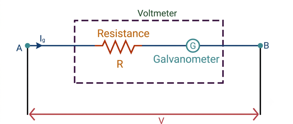
The main requirements are:
- The series resistance must be sufficiently high.
- The current through the galvanometer must not exceed its full-scale deflection current.
- The total resistance of the voltmeter should be high to minimize loading effects.
- The voltmeter must be connected in parallel with the circuit element.
Formula for Conversion of Galvanometer into Voltmeter
The formula for calculating the series resistance required to convert a galvanometer into a voltmeter is:
Where:
- = Series resistance or multiplier resistance (Ω)
- = Maximum voltage to be measured (V)
- = Full-scale deflection current of galvanometer (A)
- = Resistance of galvanometer coil (Ω)
This formula determines the resistance that must be connected in series with the galvanometer to obtain the desired voltage range.
Derivation of Galvanometer to Voltmeter Formula
Consider a galvanometer having resistance and full-scale deflection current . To convert it into a voltmeter, connect a high resistance in series with the galvanometer.
Let:
- = Resistance of galvanometer
- = Full-scale deflection current
- = Series multiplier resistance
- = Maximum voltage measured by the voltmeter
When a potential difference is applied across the combination, the same current flows through the galvanometer and series resistance because they are connected in series.
According to Ohm’s law:
Expanding the equation:
Rearranging:
Dividing both sides by :
Therefore, the required series resistance is:
This is the required expression for converting a galvanometer into a voltmeter.
Working of a Galvanometer Converted into a Voltmeter
The working of a converted voltmeter can be understood through the following steps:
- A high resistance is connected in series with the galvanometer coil.
- The combination is connected in parallel across the two points where voltage is to be measured.
- The applied potential difference produces a current through the series combination.
- The multiplier resistance restricts this current to the galvanometer’s permissible value.
- The galvanometer pointer deflects according to the current flowing through its coil.
- The instrument scale is calibrated directly in volts instead of amperes.
When the maximum rated voltage is applied, the galvanometer receives its full-scale deflection current .
Why Is High Resistance Connected in Series?
A voltmeter is designed to measure the potential difference across a circuit element without significantly changing the circuit conditions.
For this reason, a high resistance is connected in series with the galvanometer.
The main reasons are:
1. Limits the current: The series resistance prevents excessive current from flowing through the sensitive galvanometer coil.
2. Protects the instrument: It protects the moving coil from damage caused by current exceeding its rated value.
3. Reduces loading effect: A high total resistance minimizes the current drawn by the voltmeter from the circuit.
4. Increases voltage range: By selecting a suitable series resistance, the galvanometer can measure higher potential differences.
An ideal voltmeter has infinite resistance. Therefore, it draws zero current from the circuit. A practical voltmeter has very high but finite resistance.
Effective Resistance of a Converted Voltmeter
When a galvanometer is connected in series with a multiplier resistance, the total resistance of the combination is:
Where:
- = Total resistance of the voltmeter
- = Galvanometer resistance
- = Series multiplier resistance
Using the conversion formula:
Substituting:
Therefore:
This shows that the total resistance of the converted voltmeter depends on its voltage range and full-scale deflection current.
Solved Numerical Example
Question: A galvanometer has a resistance of 50 Ω and a full-scale deflection current of 1 mA. Calculate the series resistance required to convert it into a voltmeter having a range of 0–5 V.
Given data:
- Galvanometer resistance,
- Full-scale deflection current,
- Maximum voltage,
Formula:
Substituting the given values:
A resistance of 4950 Ω (4.95 kΩ) must be connected in series with the galvanometer to convert it into a 0–5 V voltmeter.
Verification:
The total resistance of the converted voltmeter is:
The current at full-scale voltage is:
Thus, the current is equal to the galvanometer’s full-scale deflection current.
Conversion of Galvanometer into Voltmeter for Different Voltage Ranges
The same galvanometer can be used to measure different voltage ranges by changing the value of the series multiplier resistance.
For a given galvanometer, the required resistance increases with the selected voltage range.
For example, consider a galvanometer with:
- Resistance = 50 Ω
- Full-scale deflection current = 1 mA
The multiplier resistance for different voltage ranges is calculated below.
| Voltage range | Series resistance |
| 1 V | 950 Ω |
| 5 V | 4,950 Ω |
| 10 V | 9,950 Ω |
| 50 V | 49,950 Ω |
| 100 V | 99,950 Ω |
Therefore, a higher voltage range requires a higher multiplier resistance.
Difference Between Galvanometer and Voltmeter
| Basis | Galvanometer | Voltmeter |
| Main function | Detects small currents | Measures potential difference |
| Circuit connection | Usually in series | In parallel |
| Resistance | Relatively low | Very high |
| Current measurement | Directly indicates small current | Draws very small current |
| Construction | Sensitive moving coil | Galvanometer with series resistance |
| Measuring range | Limited | Can be increased using multiplier resistance |
| Scale | Usually calibrated in current | Calibrated in volts |
Advantages of Converting a Galvanometer into a Voltmeter
The conversion offers several advantages:
- Wider measuring range: It allows the galvanometer to measure higher potential differences.
- Low loading effect: High internal resistance minimizes the current drawn from the circuit.
- Adjustable range: Different voltage ranges can be obtained by selecting suitable multiplier resistances.
- Cost-effective: An existing galvanometer can be modified instead of using a separate measuring mechanism.
- Simple construction: The conversion requires only an appropriate high-value series resistance.
Conclusion
The conversion of galvanometer into voltmeter is achieved by connecting a high resistance, called multiplier resistance, in series with the galvanometer. The required resistance is calculated using the formula , where is the maximum voltage range, is the full-scale deflection current, and is the galvanometer resistance.
The series resistance limits the current through the galvanometer and increases the total resistance of the instrument. As a result, the modified galvanometer can measure higher potential differences while drawing very little current from the circuit. The converted voltmeter is always connected in parallel across the component whose voltage is being measured.
Read Next:
- Galvanometer: Definition, Working Principle, Construction and Working
- Applications of Galvanometer
- Conversion of Galvanometer into Ammeter – Formula, Circuit Diagram and Derivation
- Sensitivity of Galvanometer: Formula, Types, Factors and Explanation
- Figure of Merit of a Galvanometer: Formula, Experiment and Calculation
- Galvanometer Resistance: Formula, Calculation and Measurement