Galvanometer resistance is the electrical resistance offered by the coil of a galvanometer to the flow of current. It is an important parameter that determines how much current flows through the instrument for a given applied voltage.
A galvanometer is a sensitive instrument used to detect and measure small electric currents. Its coil has a finite resistance, which affects the current flowing through the circuit and the deflection of its pointer.
The resistance of a galvanometer is also required when converting it into an ammeter or voltmeter. It helps determine the appropriate shunt resistance for an ammeter and series resistance for a voltmeter.
In this article, we will explain the galvanometer resistance formula, its relationship with current, methods of measurement, half-deflection method, numerical calculations, and galvanometer conversion.
What is Galvanometer Resistance?
A moving-coil galvanometer consists of a coil of fine insulated copper wire wound around a lightweight frame. The coil is placed between the poles of a permanent magnet.
When electric current passes through the coil, it experiences a magnetic force that produces a turning torque. This torque causes the coil and attached pointer to rotate.
The copper wire used in the coil has electrical resistance. This resistance is called galvanometer resistance, usually represented by the symbol \(G\).
The resistance depends on several factors:
- Length of the coil wire: Longer wire produces higher resistance.
- Cross-sectional area: A thicker wire has lower resistance.
- Material of the wire: Resistance depends on the resistivity of the conductor.
- Temperature: The resistance of copper generally increases with temperature.
The galvanometer resistance is usually measured in ohms (Ω).
Galvanometer Resistance Formula
The resistance of a galvanometer coil can be calculated using Ohm’s law.
The basic formula is:
Where:
- = Galvanometer resistance (Ω)
- = Voltage across the galvanometer (V)
- = Current flowing through the galvanometer (A)
The resistance of the galvanometer coil can also be calculated using the resistance formula of a conductor:
Where:
- = Resistivity of the coil wire (Ω m)
- = Total length of the coil wire (m)
- = Cross-sectional area of the wire (m²)
This formula shows that galvanometer resistance increases with wire length and resistivity. It decreases when the cross-sectional area of the wire increases.
Galvanometer Resistance and Current Relationship
The relationship between galvanometer resistance and current is explained by Ohm’s law.
According to Ohm’s law:
Rearranging the equation:
For a constant applied voltage, the current flowing through the galvanometer is inversely proportional to its resistance.
This means:
- Higher galvanometer resistance produces lower current.
- Lower galvanometer resistance allows higher current.
- For the same applied voltage, doubling the resistance reduces the current to half.
Example: Suppose a galvanometer has a resistance of 100 Ω and a voltage of 2 V is applied across it.
The current is:
If the resistance increases to 200 Ω while the applied voltage remains 2 V:
Thus, increasing galvanometer resistance reduces the current for a constant applied voltage.
Important: A galvanometer is designed to detect very small currents. The current must always remain within its rated full-scale deflection limit.
How to Calculate Galvanometer Resistance
The resistance of a galvanometer can be calculated when the voltage across its coil and the current flowing through it are known.
Using Ohm’s law:
Example: A voltage of 1.5 V is applied across a galvanometer, and a current of 5 mA flows through its coil. Calculate the galvanometer resistance.
Given:
- Voltage,
- Current,
Using the formula:
Substituting the values:
Therefore, the galvanometer resistance is 300 Ω.
Galvanometer Resistance Calculation Using Half-Deflection Method
The half-deflection method is a common experimental technique for measuring the resistance of a galvanometer.
In this method, a known resistance is connected in series with the galvanometer. A variable shunt resistance is then connected in parallel with the galvanometer to reduce its deflection to half of the original value.
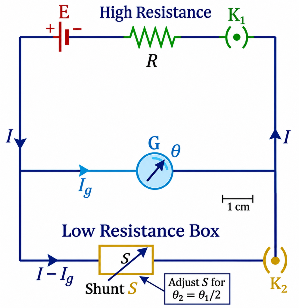
Principle of Half-Deflection Method
Initially, the galvanometer is connected in series with a known resistance and a battery of EMF .
The initial current flowing through the galvanometer is:
The galvanometer shows an initial deflection of divisions.
Now, a shunt resistance is connected in parallel with the galvanometer. The current divides between the galvanometer and the shunt resistance.
The shunt resistance is adjusted until the galvanometer deflection becomes half of its initial value.
Therefore:
Since galvanometer deflection is proportional to current:
Using the half-deflection condition, the galvanometer resistance is obtained as:
Where:
- = Galvanometer resistance (Ω)
- = Series resistance (Ω)
- = Shunt resistance producing half deflection (Ω)
This formula assumes an ideal voltage source with negligible internal resistance and a properly adjusted shunt.
Half-Deflection Method: Numerical Example
Example: A galvanometer is connected in series with a resistance of 10,000 Ω. A shunt resistance of 500 Ω is connected across the galvanometer to reduce its deflection to half. Calculate the galvanometer resistance.
Given:
- Series resistance,
- Shunt resistance,
Using the formula:
Substituting the values:
Therefore, the resistance of the galvanometer is approximately 526.32 Ω.
Galvanometer Resistance Measurement
There are different methods for measuring galvanometer resistance. The most commonly used methods include:
1. Half-Deflection Method
The half-deflection method determines galvanometer resistance by observing the change in pointer deflection when a shunt resistance is connected in parallel with the galvanometer.
The formula is:
It is widely used in school and college physics laboratory experiments.
2. Ohm’s Law Method
In this method, a known voltage is applied across the galvanometer, and the current flowing through its coil is measured.
The resistance is calculated using:
Care must be taken to use a sufficiently small current to prevent damage to the galvanometer.
3. Wheatstone Bridge Method
A Wheatstone bridge can also be used to measure galvanometer coil resistance.
The galvanometer is connected as the unknown resistance in a suitable bridge arrangement. Known resistances are adjusted until the bridge reaches its balanced condition.
At balance:
Rearranging:
Where , , and are the known bridge resistances, arranged according to the indicated ratio.
The galvanometer acts as a null detector in this measurement arrangement.
Comparison of Measurement Methods
| Method | Principle | Main advantage |
| Half-deflection | Reduction of deflection to half | Simple laboratory method |
| Ohm’s law | Voltage-current relationship | Direct calculation |
| Wheatstone bridge | Bridge balance condition | Accurate resistance measurement |
Factors Affecting Galvanometer Resistance
The resistance of a galvanometer depends mainly on the physical properties of its coil and the operating temperature.
The important factors are:
1. Length of coil wire: Resistance increases with the length of the copper wire. A longer wire provides a greater path for current.
2. Thickness of wire: A thicker wire has a larger cross-sectional area and offers less resistance.
3. Type of conductor: The resistivity of the wire material affects the total resistance. Copper is commonly used because of its good electrical conductivity.
4. Temperature: Copper has a positive temperature coefficient of resistance. Therefore, its resistance increases as temperature rises.
5. Number of turns: Increasing the number of turns generally increases the wire length and, consequently, the coil resistance, provided the wire dimensions remain unchanged.
The relationship between these factors is:
Important Points About Galvanometer Resistance
- Galvanometer resistance is represented by .
- Its SI unit is ohm (Ω).
- It depends on the length, area, and resistivity of the coil wire.
- It can be measured using the half-deflection method.
- A galvanometer has a finite internal resistance.
- Its resistance is required for ammeter and voltmeter conversion.
- The galvanometer must not be connected directly across a high-voltage supply.
Conclusion
Galvanometer resistance is an important electrical parameter that determines the relationship between applied voltage and current flowing through the galvanometer coil. It can be calculated using Ohm’s law or measured experimentally using the half-deflection method. The half-deflection formula is .
Knowledge of galvanometer resistance is essential for understanding current flow, performing electrical measurements, and converting a galvanometer into an ammeter or voltmeter. Accurate resistance measurement also helps protect the sensitive galvanometer coil from excessive current.
Read Next:
- Conversion of Galvanometer into Voltmeter: Formula, Derivation and Working
- Conversion of Galvanometer into Ammeter – Formula, Circuit Diagram and Derivation
- Applications of Galvanometer
- Galvanometer: Definition, Working Principle, Construction and Working
- Sensitivity of Galvanometer: Formula, Types, Factors and Explanation
- Figure of Merit of a Galvanometer: Formula, Experiment and Calculation