An auto transformer is a special type of transformer that works on the same principle as a two-winding transformer but uses only one winding for both primary and secondary. In this article, we explain the auto transformer working principle with diagram, how it saves copper, and its role in voltage regulation.
This guide explains the advantages and disadvantages of an auto transformer, including common disadvantages like lack of isolation and high fault current. It also helps electrical students and professionals understand the working of an auto transformer and its practical applications.
What is an Auto transformer?
An autotransformer has a single winding that functions as both primary and secondary windings, similar to a conventional transformer, and is used to adjust voltage levels. In an autotransformer, the primary and secondary windings are electrically and magnetically connected. You are probably aware that in an ordinary transformer, the primary and secondary windings are electrically and magnetically separated.
Auto transformers can be classified into two types based on their construction. The first type has a continuous winding with taps brought out at specific points to achieve the desired secondary voltage. The other type consists of two or more distinct coils that are connected electrically to form a continuous winding.
Let us now discuss the theory of autotransformers to understand how it works.
Let’s discuss the autotransformer theory to understand its working of it.
Auto transformer Working Principle
The following figure shows a circuit diagram of a typical autotransformer.
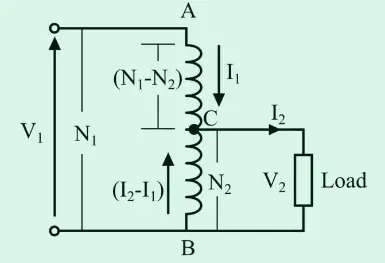
It consists of a single winding that acts as both the primary and secondary. The winding is tapped at various points to obtain the secondary winding terminals.
The winding AB and BC have N1 and N2 turns, respectively.
The primary winding AB is equipped with a tapping at C, with part of the winding BC serving as the secondary winding. The input power supply voltage is connected to winding AB, and the load is connected to winding BC. The tapping can be either fixed or variable. When an AC voltage V1 is applied across AB, it generates an alternating flux in the core, inducing an EMF E1 in winding AB. A portion of this induced EMF is conveyed to the secondary circuit.
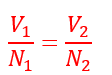
Let V1 and V2 as the primary and secondary winding voltage. The voltage per turn in the primary is,

The voltage per turn in the secondary is,

Equating the above equations, we get
Therefore, the voltage across the secondary winding is,

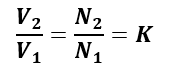
Hence, the auto transformer’s transformation ratio can be calculated as follows:
The secondary current 2 is in phase opposition to I1. Therefore, the secondary ampere-turns are opposite to primary ampere-turns. This shows that the secondary voltage is lower than the primary one, and, therefore, the current I2 is greater than I1. The current in the BC section is (I2 – I1).
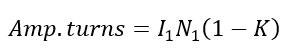
The ampere-turns in the primary and secondary of the autotransformer are the same, as per the transformer theory.
Ampere turns in section BC are equal to the current flowing in the BC section and the number of turns. The ampere turn of the auto transformer is;
As we know, an autotransformer has only one winding. This results in a copper saving compared to a two-winding transformer of the same kVA rating.
Copper Saving in Autotransformer
Auto-transformers have a single winding instead of two separate winding in a conventional transformer. The single winding of auto transformer serves both the primary and secondary sides. The portion of this single winding carries current for both the primary and secondary sides. As a result, the total length of the conductor is reduced, and copper savings are achieved.
The weight of copper required to construct a transformer depends on the ampere-turns of the transformer. Ampere-turns of AC winding (N1 – N2)I1. Hence, the weight of copper required for the part AC is directly proportional to its ampere-turns.
Ampere-turns of the BC winding, (N1 – N2)I1, directly affect the weight of copper required for part AC of the winding. Therefore, the weight of the winding is proportional to (I2 – I1)N2.
Thus, the total weight of the copper winding of the autotransformer is directly proportional to (N1 – N2)I1 + (I2 – I1)N2.

The turn ratio of the primary and secondary transformers is equal.
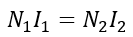
Therefore,
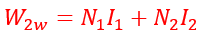
Similarly, the weight of copper required for two winding transformers is directly proportional to
The amount of copper needed for two winding transformers is directly proportional to the sum of ampere-turns of the primary and secondary winding.
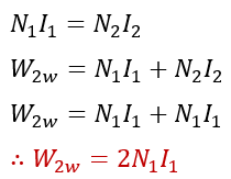
The ampere-turns of the primary and secondary of the two winding transformers are equal.
Therefore,

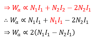
Comparing the copper weights of the transformer- autotransformer and 2-winding transformer, we get,
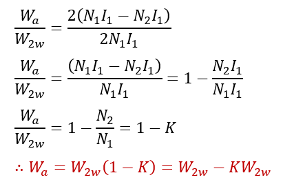
Compared to a two-winding transformer, an autotransformer saves copper. The saving of copper in an autotransformer is,

Advantages and Disadvantages of Auto Transformer
Advantages of Auto Transformer
Autotransformers have several advantages over traditional two-winding transformers. Some of the key benefits are as follows.
- Reduced Manufacturing Cost –Autotransformers require less manufacturing material in their construction, which leads to significant cost savings.
- Smaller Size – An autotransformer is about half the size of a typical two-winding transformer with the same rating.
- Reduced Core and Copper Losses –An autotransformer has fewer losses( iron and copper loss) due to reduced material.
- Better Voltage Regulation – The auto transformer has a single winding, which means its resistance and reactance are lower than the conventional transformer. The less resistance and reactance cause less voltage drop and improved voltage regulation.
- Adjustable Secondary Voltage – The voltage output of an autotransformer can be adjusted by changing the winding tapping.
- Higher Efficiency – An autotransformer is more efficient than a two-winding transformer as it can transform electrical energy through both electrical and magnetic conductions.
Disadvantages of Autotransformer
The disadvantages of autotransformers are listed below:
- High Insulation Required – The primary and secondary winding experience the same voltage stress because of a single winding. Therefore, uniform insulation is required for the transformer to withstand the high voltage.
- No Electrical Isolation between Primary and Secondary – The primary and secondary windings are electrically connected in the auto transformer, and faults like short circuits and ground faults cause more severity.
- High-Fault Current – The load is directly connected to the supply during short circuit fault conditions, and the magnitude of the fault current is high because of low internal impedance.
- Full Supply Voltage at Output under Open Circuit Fault Condition – In an autotransformer, the full supply voltage will appear across the load if there is an open circuit fault in the common part of the winding.
Applications of Auto Transformer
Autotransformers find various applications in electrical engineering. Some of the most common uses include:
- Autotransformers are commonly utilized in testing laboratories for the purpose of testing repaired electrical devices.
- Autotransformers compensate for line voltage drops in transmission and distribution lines.
- Resistance heating uses temperature adjustment, and this is achieved through the use of a temperature controller and auto transformer.
- Autotransformers are commonly used as a starter for induction motors. It is also used to regulate the speed of the motor.
- A voltage stabilizer predominantly uses an autotransformer as its primary component.
Conclusion
In this article, we have covered everything about autotransformers. An autotransformer is a type of electrical transformer that has a single winding and is used for regulating the output voltage.
Read Next: