The ammeter connection in a circuit is important for accurately measuring the electric current flowing through an electrical or electronic circuit. An ammeter is an electrical measuring instrument used to measure the current drawn by a load. It is always connected in series with the load so that the same current flows through both the ammeter and the load.
The ammeter is always connected in series with the load whose current is to be measured. This connection ensures that the same current flowing through the load also passes through the ammeter.
In this article, we will explain how to connect an ammeter in a circuit, why it is connected in series, its circuit diagram, connection procedure, and common mistakes to avoid.
How Is an Ammeter Connected in a Circuit?
An ammeter is connected in series with the electrical component or load whose current needs to be measured.
In a series connection, the circuit current passes through the ammeter before flowing through the load. Therefore, the current entering and leaving the load is also the current measured by the ammeter.
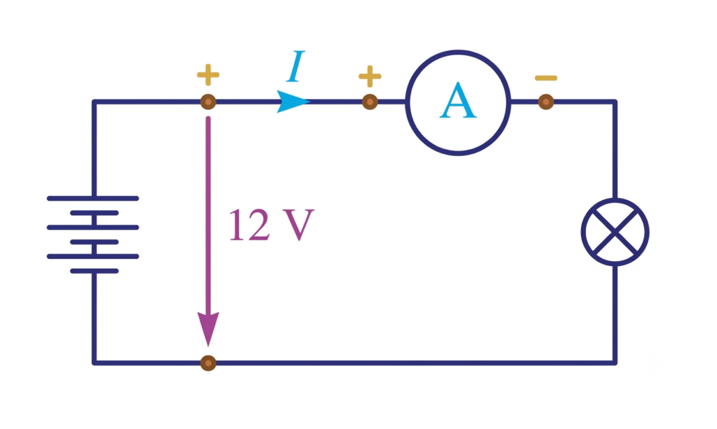
Important points about ammeter connection:
- An ammeter is connected in series with the load.
- It has very low internal resistance.
- The entire circuit current passes through the ammeter.
- The positive terminal of the ammeter is connected towards the positive side of the supply.
- The negative terminal is connected towards the negative side of the supply.
Ammeter Connection Diagram
The following diagram illustrates the practical connection of an ammeter in a DC circuit.
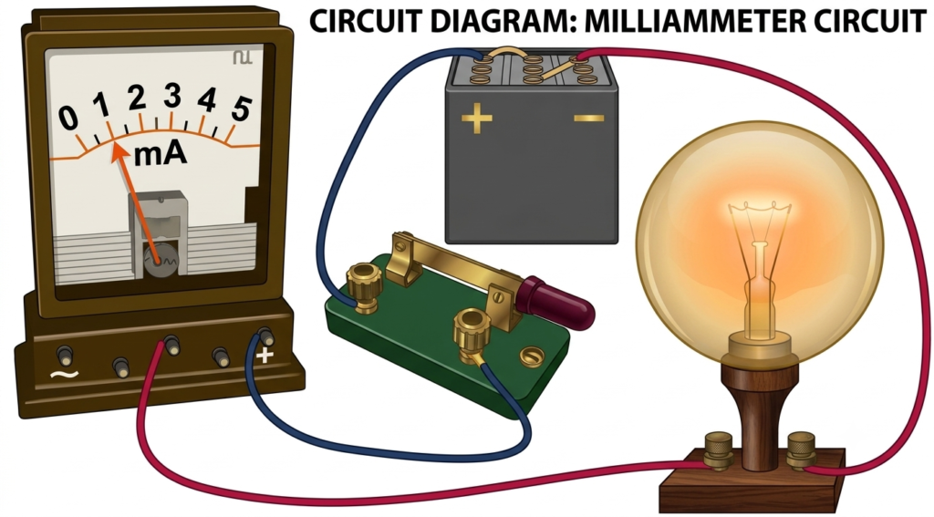
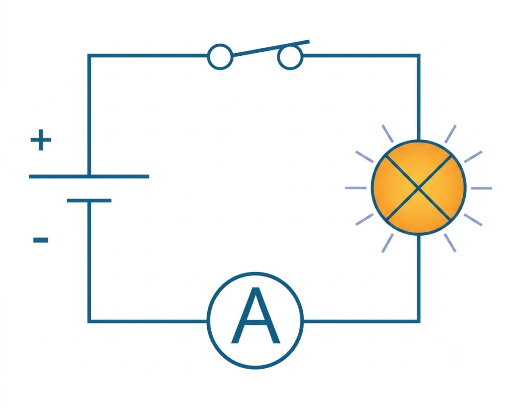
n this circuit, a battery supplies electrical energy to a lamp. The ammeter is connected in series between the power supply and the lamp.
When the switch is closed, current flows through the complete circuit. The ammeter measures the current flowing through the lamp.
The current path is:
Battery → Ammeter → Lamp → Battery
This arrangement ensures that the ammeter measures the actual load current.
Why Is an Ammeter Connected in Series?
An ammeter measures the current flowing through an electrical circuit. To measure this current accurately, the instrument must carry the same current as the load.
There are three main reasons for connecting an ammeter in series.
1. To Measure the Actual Circuit Current
In a series circuit, the same current flows through all connected components. Therefore, connecting the ammeter in series allows it to measure the current flowing through the load.
2. Low Internal Resistance
An ammeter has very low internal resistance. This minimizes the voltage drop across the instrument and prevents it from significantly affecting the circuit current.
If an ammeter had high resistance, it would reduce the current flowing through the circuit and produce an inaccurate measurement.
3. To Avoid Short Circuits
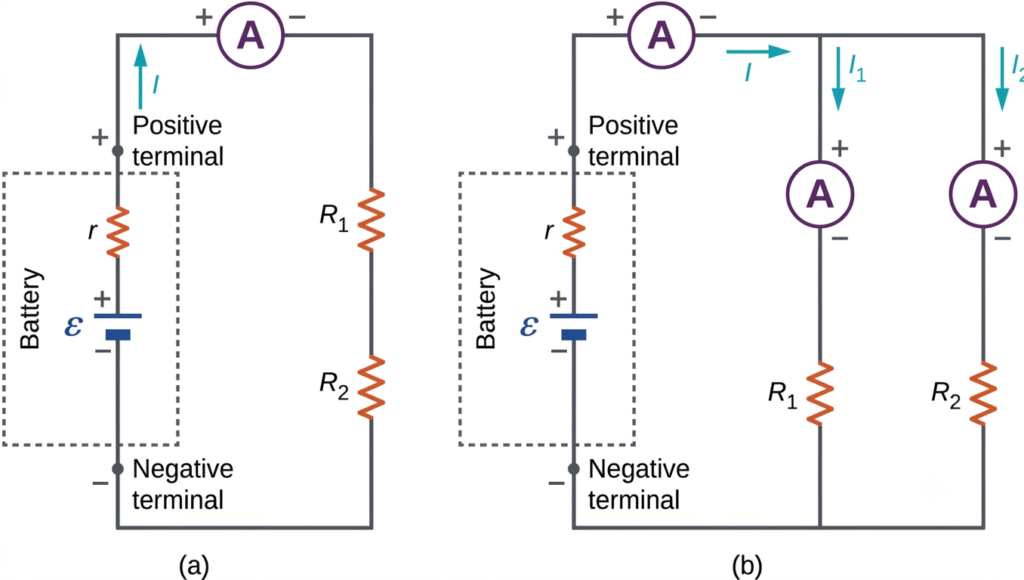
An ammeter should never be connected directly across a voltage source or in parallel with a load.
Since an ammeter has very low resistance, connecting it in parallel can cause a very high current to flow through the instrument. This may damage the ammeter, blow its fuse, or create a short circuit.
Steps to Connect an Ammeter in a Circuit
Follow these steps to connect an ammeter correctly:
1. Switch off the power supply: Before making connections, disconnect the electrical supply to ensure safety.
2. Identify the circuit path: Locate the load whose current needs to be measured.
3. Open the circuit: Disconnect one wire in the circuit to create a suitable point for inserting the ammeter.
4. Connect the ammeter in series: Connect the positive terminal of the ammeter towards the positive side of the supply and the negative terminal towards the load.
5. Select the correct current range: Choose a suitable range based on the expected circuit current. If the current is unknown, start with the highest available range.
6. Switch on the supply: Restore the power supply and observe the ammeter reading.
7. Record the current: Read the value indicated by the instrument and note the current in amperes (A).
Safety precaution: Never change the ammeter connection while the circuit is energized.
Ammeter Connection in AC and DC Circuits
An ammeter can be used in both AC and DC circuits, depending on its construction and operating principle.
Ammeter Connection in a DC Circuit
In a DC circuit, the ammeter is connected in series with the load. For a conventional polarity-sensitive DC ammeter, connect its positive terminal towards the positive supply terminal.
A PMMC (Permanent Magnet Moving Coil) ammeter is commonly used for DC current measurement.
Ammeter Connection in an AC Circuit
In an AC circuit, the ammeter is also connected in series with the load. However, the current direction reverses periodically.
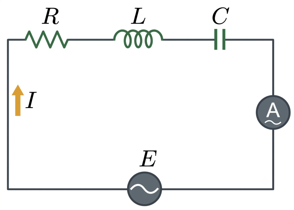
Moving iron and electrodynamometer-type ammeters can measure AC current. A suitable AC digital ammeter can also be used.
Note: Always select an instrument rated for the type of current and expected measurement range.
What Happens If an Ammeter Is Connected in Parallel?
Connecting an ammeter in parallel is a serious connection mistake.
An ammeter has very low internal resistance. When connected directly across a voltage source, it provides a low-resistance path for current.
According to Ohm’s law:
Where:
- = Current in amperes
- = Applied voltage in volts
- = Resistance in ohms
Since the internal resistance of an ammeter is very low, the current can become extremely high.
This can result in:
- Blowing of the ammeter fuse.
- Damage to the measuring instrument.
- Overheating of connecting wires.
- Short circuit in the electrical supply.
- Possible electrical hazards.
Therefore, always connect an ammeter in series with the load.
Numerical Example of Ammeter Connection
Problem: A 12 V DC supply is connected to a 6 Ω resistor. Calculate the current indicated by an ammeter connected in series with the resistor.
Given:
- Supply voltage,
- Load resistance,
Using Ohm’s law:
Substituting the values:
The ammeter will indicate 2 A, assuming an ideal ammeter with negligible internal resistance.
Precautions While Connecting an Ammeter
The following precautions should be followed while using an ammeter:
- Always connect the ammeter in series with the load.
- Never connect an ammeter directly across a power supply.
- Select the correct current measurement range.
- Check the polarity before connecting a DC ammeter.
- Ensure that the current rating of the instrument is not exceeded.
- Use properly rated connecting wires and terminals.
- Switch off the supply before changing circuit connections.
- Use an appropriately rated and fused instrument for the circuit.
Conclusion
An ammeter is always connected in series with the load to measure the current flowing through an electrical circuit. Its very low internal resistance ensures that it has minimal influence on the circuit current. The correct polarity and measurement range must also be considered when making connections.
Never connect an ammeter in parallel with a load or directly across a voltage source, as this can result in excessive current and damage to the instrument.
Read Next:
- Ammeter Shunt: Definition, Working Principle, Construction, Circuit Diagram, Formula and Applications
- Ammeter: Definition, Symbol, Working Principle, Types and Applications
- Hot Wire Ammeter- Construction, Working Principle & Diagram
- Moving Iron Instrument: Working Principle, Construction, Types, Theory and Applications
- Moving Coil Instrument: Working Principle, Construction, Types, Advantages and Errors
- Galvanometer: Definition, Construction, Working