A wattmeter is an electrical measuring instrument used to determine the active power consumed or produced by an electrical circuit. It measures power in watts (W) and is widely used in electrical laboratories, industrial plants, power systems, and electronic equipment testing.
Knowing the power consumed by electrical equipment helps engineers evaluate performance, identify energy losses, troubleshoot electrical faults, and improve operating efficiency. Unlike a voltmeter, which measures voltage, or an ammeter, which measures current, a wattmeter measures the actual active power in a circuit.
Wattmeters are available in analog and digital designs. Depending on the application, they can measure power in single-phase or three-phase systems and may also provide readings for voltage, current, power factor, and frequency.
In this article, you will learn what a wattmeter is, its working principle, different types, advantages, and applications in electrical engineering.
What Is a Wattmeter?
A wattmeter is an instrument that measures the active electrical power transferred to a load or generated by a source. Its reading is expressed in watts or kilowatts.
In a DC circuit, electrical power is calculated by multiplying voltage by current:
Where:
- = Electrical power in watts (W)
- = Voltage in volts (V)
- = Current in amperes (A)
In a single-phase AC circuit, the active power depends on the voltage, current, and power factor:
Where:
- = RMS voltage
- = RMS current
- = Power factor
- = Phase angle between voltage and current
For example, suppose an AC load operates at 230 V, draws 5 A, and has a power factor of 0.8.
Therefore, the active power consumed by the load is 920 W.
This example illustrates why simply multiplying voltage by current does not always give the actual active power in an AC circuit.
Working Principle of a Wattmeter
The working principle of a wattmeter depends on its construction. A traditional electrodynamic wattmeter operates through the interaction of magnetic fields produced by its current coil and pressure coil. Digital wattmeters use electronic sensing circuits to measure voltage and current and calculate their instantaneous product.
Wattmeter diagram is shown in the image below.
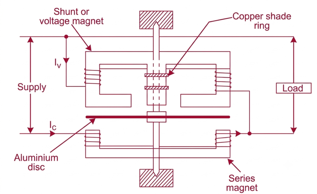
1. Current Coil
The current coil, also known as the series coil, is connected in series with the load. It carries the load current and produces a magnetic field proportional to that current.
The current coil is generally designed with a low resistance so that it causes only a small voltage drop in the circuit.
2. Pressure Coil
The pressure coil, also called the voltage coil or potential coil, is connected across the load. It has a relatively high resistance and carries a small current proportional to the applied voltage.
In an electrodynamic wattmeter, the magnetic field produced by the pressure coil interacts with the field produced by the current coil.
3. Power Measurement
The interaction between the two magnetic fields generates a deflecting torque. Under normal operating conditions, the average torque is proportional to the active power in the circuit.
The pointer moves over a calibrated scale to indicate the power reading.
In a digital wattmeter, voltage and current signals are sampled electronically. The instrument calculates instantaneous power and averages or integrates the measurements as required.
For a single-phase AC circuit, the average active power can be represented as:
Where:
- = Average active power
- = Instantaneous voltage
- = Instantaneous current
- = Measurement interval
This method allows a suitable digital wattmeter to measure active power even when voltage and current waveforms are not perfectly sinusoidal.
Construction of an Electrodynamic Wattmeter
A traditional electrodynamic wattmeter consists of the following main components.
Current Coil
The current coil consists of a few turns of thick wire and is connected in series with the load. Its purpose is to produce a magnetic field corresponding to the load current.
Pressure Coil
The pressure coil consists of many turns of fine wire and is connected across the load through a high resistance. It produces a magnetic field corresponding to the supply voltage.
Moving Coil and Pointer
The moving coil is mounted on a spindle and carries a pointer that moves over a calibrated scale. The interaction between the magnetic fields of the current and pressure coils produces the deflecting torque.
Controlling Springs
Springs provide the controlling torque needed to establish the pointer’s final position. They also serve as electrical connections to the moving coil in many designs.
Damping Mechanism
A damping mechanism helps the pointer settle quickly at its final reading without excessive oscillation.
Calibrated Scale
The scale is marked in watts or other appropriate power units, allowing the measured active power to be read directly.
Types of Wattmeters
Wattmeters can be classified according to their construction, measurement method, and the electrical systems in which they are used.
1. Analog Wattmeter
An analog wattmeter displays the measured power through a pointer moving across a graduated scale. Electrodynamic wattmeters are a common example used in electrical measurement laboratories.
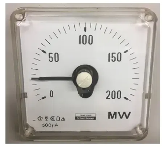
These instruments provide a direct visual indication of power without requiring a digital display.
Advantages:
- Simple operating principle
- Direct indication of power
- Useful for laboratory demonstrations and basic electrical testing
- No digital processing or display is required
Limitations:
- Reading accuracy depends partly on scale resolution and viewing angle
- Mechanical movement may be affected by wear or vibration
- Data logging and remote monitoring are generally unavailable
2. Digital Wattmeter
A digital wattmeter measures electrical signals electronically and displays the calculated power numerically.
It commonly uses voltage and current sensors, analog-to-digital converters, and a processing circuit to calculate active power.
Depending on the model, a digital wattmeter may also display RMS voltage, RMS current, power factor, frequency, and other parameters.
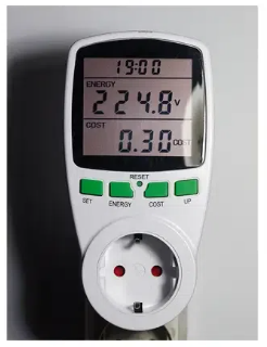
Advantages:
- Easy-to-read numerical results
- Good measurement resolution
- Reduced errors associated with reading an analog scale
- Additional measurement functions in multifunction models
- Data storage and communication in supported instruments
Applications:
- Electrical testing laboratories
- Appliance power measurement
- Electronic circuit testing
- Industrial power monitoring
3. Electrodynamic Wattmeter
An electrodynamic wattmeter uses the interaction between the magnetic fields of fixed and moving coils to measure power.
The fixed coils generally form the current circuit, while the moving coil forms the voltage circuit. The resulting deflecting torque is related to the average power consumed by the load.
These instruments can be used for both AC and DC power measurement. Their performance depends on correct connections, calibration, and the specified operating range.
4. Induction Wattmeter
An induction type wattmeter operates on the principle of electromagnetic induction to measure electrical power in AC circuits.
It uses alternating magnetic fluxes produced by current and voltage coils to induce eddy currents in a moving aluminium disc. The interaction between these fluxes and the induced currents generates a driving torque, causing the disc or moving system to respond according to the power consumed by the load.
Induction wattmeters are suitable only for AC measurements and are commonly used in applications where electromagnetic induction is used to determine electrical power.
5. Single-Phase Wattmeter
A single-phase wattmeter measures active power in a single-phase electrical circuit.
Its current circuit is connected in series with the load, and its voltage circuit is connected across the load. It is commonly used to measure power consumed by household appliances, single-phase motors, heaters, and laboratory loads.
Single-phase wattmeters are available in analog and digital versions.
6. Three-Phase Wattmeter
A three-phase wattmeter measures active power in a three-phase electrical system. It is used in industrial plants, commercial buildings, motor installations, and power distribution systems.
Depending on the instrument design, it may use multiple measuring elements to determine the total power across the three phases.
For balanced three-phase loads, active power can be calculated using:
Where:
- = Total active power
- = Line-to-line voltage
- = Line current
- = Power factor
For unbalanced systems, total power must be determined using an appropriate measurement method that accounts for the individual phases.
7. Clamp-On Wattmeter
A clamp-on wattmeter measures current using a clamp-type sensor placed around a conductor. Voltage is measured through suitable leads or another supported sensing arrangement.
The instrument combines voltage and current measurements to calculate power. Some clamp meters measure only current, so a clamp meter should not be assumed to be a wattmeter unless it explicitly supports power measurement.
Clamp-on wattmeters are useful when interrupting the circuit to insert a conventional current coil is inconvenient.
Applications:
- Electrical maintenance
- Motor testing
- Troubleshooting electrical loads
- Field measurements in distribution systems
8. High-Frequency and RF Wattmeter
An RF wattmeter measures power in radio-frequency circuits and communication systems. Its design differs from conventional 50 Hz power instruments because it must operate over a specified frequency range and handle high-frequency signals.
Depending on the model, an RF wattmeter may measure forward power, reflected power, or other RF parameters.
Applications:
- Radio transmitters
- Antenna systems
- Communication equipment
- RF laboratories
Properties of a Wattmeter
A wattmeter has several important properties that determine its measurement capability, accuracy, and suitability for different electrical applications.
1. Electrical Power Measurement
The primary function of a wattmeter is to measure active electrical power, expressed in watts (W). In AC circuits, it accounts for the phase relationship between voltage and current to determine the actual power transferred to a load.
Some specialized wattmeters and power analyzers can also measure reactive power, apparent power, and power factor. These additional functions depend on the instrument’s design.
2. Multiple Measurement Ranges
Wattmeters are available with different voltage and current ranges to accommodate various power levels. Some instruments have manually selectable ranges, while advanced digital models provide automatic range selection.
Choosing the correct range helps obtain suitable measurement resolution and prevents the instrument from being overloaded.
3. Measurement Accuracy
Accuracy indicates how closely the wattmeter’s reading corresponds to the actual electrical power. It depends on the instrument’s accuracy class, calibration, operating conditions, and measurement range.
High-accuracy wattmeters are particularly useful in electrical laboratories, equipment testing, power-system analysis, and industrial applications where reliable measurements are essential.
4. AC and DC Compatibility
Depending on its construction, a wattmeter can measure power in DC circuits, AC circuits, or both.
Electrodynamic wattmeters can be used for both AC and DC measurements. Electronic wattmeters may also support both, provided their specifications allow it.
For AC measurements, the instrument must account for the relationship between voltage and current. Three-phase power measurement requires a suitable meter configuration for the particular supply system.
5. Measurement Configuration
Wattmeters are available in different configurations depending on the electrical system and the quantities being measured.
For example, a single-phase wattmeter generally uses a current circuit connected in series with the load and a voltage circuit connected across it. Three-phase power can be measured using appropriate two-element or three-element arrangements.
The number of measuring elements depends on the circuit configuration and the measurement method; it does not, by itself, determine whether the instrument measures active or reactive power.
Characteristics of a Wattmeter
In addition to its basic measurement properties, a wattmeter has practical characteristics that influence its operation and usability.
1. Overload Protection
Many modern wattmeters include protective features to reduce the risk of damage from excessive voltage or current. Depending on the model, these may include input protection, fuses, overload warnings, or automatic shutdown.
The instrument must still be operated within its specified electrical ratings.
2. Analog or Digital Display
Wattmeters use different display technologies according to their design.
- Analog wattmeter: Uses a pointer and calibrated scale to indicate the measured power.
- Digital wattmeter: Displays the measured value numerically and may provide additional electrical parameters.
Digital displays simplify reading, while analog instruments are useful for observing changes in measurements continuously.
3. Data Logging and Communication
Advanced digital wattmeters may store measurement records for later analysis. Some models support communication interfaces such as RS-485, USB, or Ethernet, allowing measured data to be transferred to computers or monitoring systems.
These features are useful for remote monitoring, automated testing, and industrial energy-management applications.
4. Portability and Physical Design
Wattmeters are manufactured in different sizes and designs to suit their intended applications.
Handheld instruments are convenient for field measurements and electrical maintenance. Bench-type wattmeters are commonly used in laboratories and testing facilities, while panel-mounted power meters support continuous monitoring in electrical distribution boards.
5. Frequency Response
The frequency response specifies the range of signal frequencies over which a wattmeter can measure power within its stated performance limits.
Conventional wattmeters are generally designed for standard power frequencies, whereas specialized instruments are required for high-frequency or radio-frequency applications.
6. Input Impedance and Circuit Loading
The electrical characteristics of the wattmeter’s voltage and current inputs can influence measurement accuracy.
The voltage circuit should draw an appropriate amount of current, while the current circuit should introduce an acceptably small voltage drop. Proper instrument design minimizes the effect of the measuring device on the circuit being tested.
7. Additional Measurement Functions
Depending on the model, a wattmeter may also measure voltage, current, power factor, frequency, apparent power, and reactive power.
Some advanced instruments can calculate energy consumption over time and record changes in power. These additional functions make them useful for comprehensive electrical system analysis.
8. Calibration and Stability
A wattmeter should maintain its specified accuracy under its intended operating conditions. Calibration helps verify its readings against recognized reference standards.
Measurement stability can be influenced by temperature, component ageing, electromagnetic interference, and operating conditions. Periodic verification is important where measurement accuracy is critical.
Advantages of Using a Wattmeter
Wattmeters help engineers, technicians, and facility operators understand the electrical power requirements of equipment.
Accurate Power Measurement
A suitable wattmeter measures active power directly, accounting for the relationship between voltage and current rather than relying only on their magnitudes.
Improved Energy Efficiency
Power measurements help identify equipment that draws more power than expected. Engineers can investigate operating conditions, loading, and possible inefficiencies.
Electrical Troubleshooting
Comparing power readings with expected values can help identify incorrect connections, abnormal loading, or equipment performance problems.
Motor Performance Evaluation
Wattmeters can measure the electrical input power of motors. When combined with mechanical output measurements, these readings can be used to evaluate motor efficiency.
Cost and Operating Analysis
Power measurements help assess equipment operating costs when combined with operating time and electricity tariff information.
Support for Testing and Research
Wattmeters are essential in electrical laboratories, product development, equipment testing, and power-system analysis.
Applications of Wattmeters
Wattmeters are used in a wide range of electrical and electronic applications.
1. Domestic Appliances
Wattmeters can measure the power consumed by compatible household appliances, such as heaters, fans, refrigerators, and other electrical equipment. Plug-in power meters are particularly useful for appliances connected through suitable socket adapters.
2. Industrial Equipment
Industrial engineers use wattmeters to monitor the input power of motors, pumps, compressors, conveyors, and production machinery.
Power measurements can help assess loading conditions and identify unexpected changes in equipment operation.
3. Electrical Laboratories
Wattmeters are used in laboratory experiments involving DC circuits, single-phase AC systems, three-phase power, transformers, and electrical machines.
They help students and engineers verify theoretical calculations through practical measurements.
4. Power Generation and Distribution
Power stations and electrical substations use suitable power-measuring instruments to monitor active power flow, generator output, and electrical loading.
For large installations, wattmeters or multifunction power meters may operate through instrument transformers.
5. Renewable Energy Systems
Wattmeters can measure electrical power produced by solar inverters, wind-energy systems, and other power-conversion equipment. Appropriate instruments can help evaluate system output and identify performance changes.
6. Building Energy Management
Commercial and residential buildings use power meters to monitor lighting systems, HVAC equipment, pumps, and other major electrical loads.
The recorded data can help building managers identify opportunities to reduce unnecessary electricity consumption.
7. Electronic Equipment Testing
Digital wattmeters are used to measure power consumed by electronic devices, power supplies, chargers, and other electrical products. Suitable high-frequency instruments are also used for RF equipment testing.
Difference Between a Wattmeter and an Energy Meter
A wattmeter and an energy meter measure different electrical quantities.
| Parameter | Wattmeter | Energy meter |
| Main function | Measures active power | Measures accumulated electrical energy |
| Common unit | W or kW | Wh or kWh |
| Measurement | Power at a given time or over a defined measurement interval | Energy accumulated over time |
| Typical application | Equipment testing and power monitoring | Electricity billing and energy accounting |
| Example reading | 1,000 W | 5 kWh consumed over a period |
A wattmeter indicates how quickly electrical energy is being used or produced. An energy meter records the total energy transferred over a period.
Precautions When Using a Wattmeter
Correct installation and operation are necessary for reliable measurements.
- Connect the current coil in series with the load and the voltage coil across the load, following the instrument’s wiring diagram.
- Check the instrument’s voltage, current, frequency, and power ratings before use.
- Observe the specified polarity of the terminals, particularly for DC measurements.
- Select the correct range to prevent overloading the instrument.
- Use suitable current transformers or voltage transformers where required.
- Ensure that measurement leads, insulation, and connections are appropriate for the circuit voltage and environment.
- Follow electrical isolation and safety procedures when installing or removing connections.
- For electronic loads with distorted waveforms, use a wattmeter with suitable bandwidth and true-power measurement capability.
Conclusion
A wattmeter is an essential electrical instrument for measuring active power in AC and DC circuits. Traditional electrodynamic wattmeters use the interaction of magnetic fields to produce a power-dependent deflection, while digital wattmeters calculate power electronically from voltage and current measurements.
Different wattmeters are available for single-phase circuits, three-phase systems, industrial maintenance, electronic testing, and high-frequency applications. Selecting the correct instrument requires checking the supply type, voltage and current ranges, frequency response, accuracy, and measurement requirements.
By providing reliable power readings, wattmeters support electrical troubleshooting, equipment testing, performance evaluation, and energy-efficiency improvements.
Read Next:
- Types of Energy Meters and Their Working Principles
- Three Phase Energy Meter Connection Diagram
- Calculation of Multiplication Factor of Energy Meters
- Clamp Meter Working Principle, Diagram & Uses
- Single Phase Energy Meter Calibration
- Single Phase Energy Meter: Construction, Working Principle, Types
- Single Phase Energy Meter Connection Diagram: Wiring, Terminals