The three wattmeter method is used to measure the total active power in a three-phase electrical system, particularly in a three-phase, four-wire circuit with a neutral connection. It is suitable for both balanced and unbalanced loads, making it useful for measuring power in industrial electrical installations.
In this method, three wattmeters are connected to measure the power associated with the three phases individually. The total three-phase power is obtained by adding the algebraic readings of all three wattmeters.
This article explains the three wattmeter method, its connection diagram, working principle, mathematical formula, applications, and the difference between three-wattmeter and two-wattmeter methods.
What Is the Three Wattmeter Method?
The three wattmeter method is a technique for measuring the total active power consumed by a three-phase AC circuit using three separate wattmeters.
Each wattmeter measures the power associated with one phase. Its current coil is connected in series with the corresponding phase conductor, while its pressure coil is connected between that phase and a common reference point, usually the neutral.
The method is particularly useful for a three-phase, four-wire system with an unbalanced load, because the power consumed by each phase can be different.
The total power is calculated by adding the individual wattmeter readings algebraically.
Three Wattmeter Method Connection Diagram
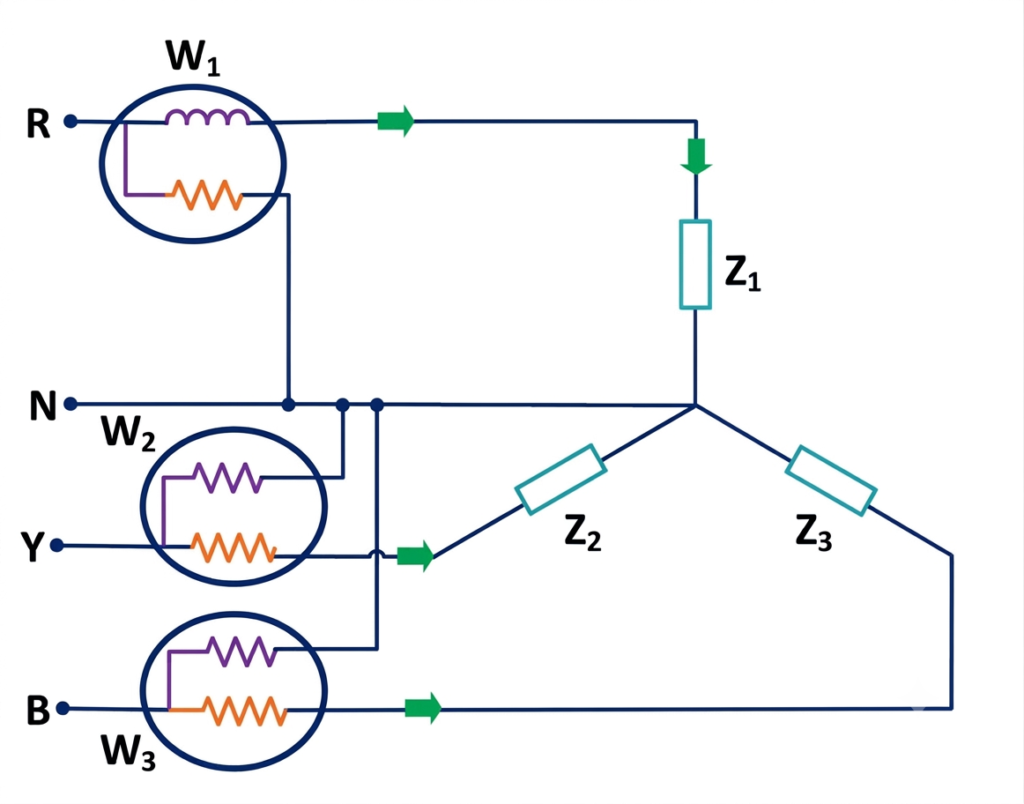
In a three-phase, four-wire star-connected system, the three wattmeters are connected as follows:
- Wattmeter measures the power associated with phase R.
- Wattmeter measures the power associated with phase Y.
- Wattmeter measures the power associated with phase B.
- Each current coil is connected in series with its respective phase.
- Each pressure coil is connected between its phase and the common neutral point.
The neutral connection provides the reference voltage for the three pressure coils.
Important: The current coil and pressure coil terminals must be connected according to the wattmeter manufacturer’s instructions and rated circuit conditions.
Working Principle of the Three Wattmeter Method
The three wattmeter method works by measuring the active power of each phase separately. The total power is obtained by adding the three readings.
1. Power measurement in phase R
The first wattmeter measures the voltage between phase R and neutral, along with the current flowing through phase R.
For a sinusoidal AC load, its reading is:
Where:
- = RMS voltage between phase R and neutral
- = RMS current in phase R
- = phase angle between phase voltage and phase current
2. Power measurement in phase Y
The second wattmeter measures the active power associated with phase Y.
Where is the RMS phase-to-neutral voltage, is the phase current, and is the phase power-factor angle.
3. Power measurement in phase B
The third wattmeter measures the active power associated with phase B.
Where is the RMS phase-to-neutral voltage, is the phase current, and is the phase power-factor angle.
The total active power is the algebraic sum of the three readings.
Three Wattmeter Method Formula
The total active power in a three-phase, four-wire system is:
Where:
- = total active power in watts (W)
- = reading of the first wattmeter
- = reading of the second wattmeter
- = reading of the third wattmeter
For a balanced load, all three phases have equal voltage, current, and power factor. Therefore:
Hence, the total power becomes:
For a balanced star-connected load:
Alternatively, using line voltage and line current:
Where is the line-to-line voltage, is the line current, and is the power factor.
These balanced-load formulas apply when the phase quantities are equal and the supply is balanced.
Numerical Example of the Three Wattmeter Method
A three-phase, four-wire electrical system has the following wattmeter readings:
Calculate the total active power consumed by the load.
Solution
The total power is the algebraic sum of the wattmeter readings.
Substituting the values:
Therefore, the total active power consumed by the three-phase load is 7.3 kW.
If any wattmeter indicates reverse deflection, its reading must be treated as negative after the appropriate polarity or connection procedure is followed.
Three Wattmeter Method and Blondel’s Theorem
Blondel’s theorem determines the number of wattmeters required to measure total power in a polyphase system.
According to the theorem, for a system supplied through (K) conductors, the total power can generally be measured using (K-1) wattmeters, provided the connections are made appropriately.
Therefore:
- A three-phase, three-wire system can be measured using two wattmeters.
- A three-phase, four-wire system can be measured using three wattmeters when the neutral conductor is used as the common reference.
For a three-phase, four-wire system, the three-wattmeter method is especially useful when the load is unbalanced and the neutral carries current.
Three Wattmeter Method for Balanced and Unbalanced Loads
Balanced load
In a balanced three-phase load, the phase impedances are equal, and the phase currents have equal magnitudes. Under balanced supply conditions, the three wattmeters measure equal power.
Thus:
Unbalanced load
In an unbalanced load, the phase currents, phase power factors, and individual phase powers may differ. The three wattmeter readings are therefore not necessarily equal.
The total power is still calculated as:
This makes the method suitable for measuring the total active power of unbalanced loads in a three-phase, four-wire system.
Applications of the Three Wattmeter Method
The three wattmeter method is used in electrical power measurement and testing applications, including:
- Measuring power in three-phase, four-wire distribution systems.
- Testing unbalanced three-phase loads in industrial installations.
- Monitoring phase-wise power consumption in electrical panels.
- Measuring the power used by three-phase equipment when phase-by-phase information is required.
- Laboratory testing of three-phase circuits and electrical machines.
- Investigating unequal loading between phases in distribution systems.
Advantages of the Three Wattmeter Method
- Measures total active power in balanced and unbalanced three-phase, four-wire systems.
- Provides individual phase-power readings.
- Helps identify differences in power consumption between phases.
- Does not require the load to be balanced.
- Can be used with resistive, inductive, and mixed electrical loads, subject to instrument suitability.
Limitations of the Three Wattmeter Method
- Requires three wattmeters, increasing equipment and wiring requirements.
- Needs access to the neutral reference for the standard three-phase, four-wire arrangement.
- Requires more connections and installation space than the two-wattmeter method.
- May be unnecessary when only total power in a three-phase, three-wire system is required.
Difference Between the Three Wattmeter Method and the Two Wattmeter Method
| Feature | Three wattmeter method | Two wattmeter method |
| Number of wattmeters | Three | Two |
| Typical application | Three-phase, four-wire system | Three-phase, three-wire system |
| Balanced load | Suitable | Suitable |
| Unbalanced load | Suitable for four-wire systems | Suitable for three-wire systems |
| Individual phase power | Measured directly in the standard phase-to-neutral arrangement | Not measured directly by each wattmeter |
| Total power calculation | P = W1 + W2 + W3 | P = W1 + W2 |
| Neutral connection | Used in the standard four-wire arrangement | Not required |
The two-wattmeter method can measure total active power in a three-phase, three-wire system even when the load is unbalanced. The three-wattmeter method is generally preferred when measuring individual phase powers in a four-wire system.
Conclusion
The three wattmeter method of three-phase power measurement is a practical technique for measuring total active power in a three-phase, four-wire electrical system. It uses three wattmeters, each measuring the power associated with one phase.
The total power is calculated by adding the three readings algebraically: The method is suitable for both balanced and unbalanced loads and provides useful phase-wise power information. For three-phase, three-wire systems, the two-wattmeter method is generally sufficient when only total active power is required.
Read Next:
- Wattmeter: Working Principle, Types, Advantages, and Applications
- Induction Type Wattmeter: Construction, Working Principle, Diagram, and Torque Equation
- Two Wattmeter Method: Circuit Diagram, Working Principle, and Derivation
- Electrodynamometer Type Wattmeter: Construction, Working Principle, Torque Equation
- Wattmeter Connection: Diagram and Methods Explained