Single phase energy meter calibration is the process of checking and correcting an energy meter’s accuracy by comparing its readings with a traceable reference standard under controlled electrical conditions. It helps ensure that the meter measures electrical energy consumption accurately for billing, energy audits, and power monitoring.
The calibration procedure involves checking the meter at different load conditions, measuring its percentage error, and making adjustments where supported by the meter design. Both electromechanical and electronic energy meters can be tested using a suitable calibration setup.
This article explains the purpose of single phase energy meter calibration, applicable standards, required equipment, test setup, step-by-step calibration procedure, error calculation, and safety precautions.
What Is Single Phase Energy Meter Calibration?
Single phase energy meter calibration is a process used to verify the accuracy of a meter that measures electrical energy consumption in a single-phase AC supply system.
During calibration, the energy recorded by the meter under test is compared with the energy measured by a calibrated reference meter or precision power analyzer. The comparison is performed at specified voltage, current, power factor, and load conditions.
The difference between the two measurements indicates the meter’s error. If the error exceeds the permissible limit for its accuracy class, the meter may require adjustment, repair, or replacement.
Why Is Energy Meter Calibration Necessary?
Energy meter calibration is important for the following reasons:
- Accurate electricity billing: Ensures that recorded energy consumption is within the applicable accuracy limits.
- Energy auditing: Improves the reliability of energy consumption data used for electrical performance analysis.
- Detection of measurement errors: Identifies errors caused by component aging, circuit drift, incorrect installation, or damage.
- Compliance with standards: Verifies whether the meter meets the applicable accuracy requirements.
- Reliable energy monitoring: Helps maintain confidence in energy measurements used for operational decisions.
Standards for Single Phase Energy Meter Calibration
The applicable standard depends on the meter type, installation, country, and regulatory requirements.
| Standard | Purpose |
| IEC 62052-11 | General requirements and test conditions for electricity metering equipment |
| IEC 62053 series | Meter-specific accuracy requirements and tests for applicable classes of electricity meters |
| ANSI C12.1 | Requirements for electricity meters used in North American applications |
| ANSI C12.20 | Accuracy requirements for applicable precision electricity meters |
The relevant edition and specific part of the standard should be checked before testing. In India, calibration and verification must also follow applicable Central Electricity Authority requirements, Legal Metrology provisions where applicable, and the procedures of the authorized utility or laboratory.
Equipment Required for Energy Meter Calibration
The following equipment is generally required for single phase energy meter calibration:
- Reference energy meter: A calibrated meter with suitable accuracy and traceability.
- Precision power analyzer: Measures voltage, current, power, power factor, and energy.
- Stable AC voltage source: Supplies the required test voltage.
- Variable current source: Provides controlled current at different load points.
- Phantom load or meter test bench: Allows voltage and current to be controlled independently while minimizing power consumption.
- Resistive and inductive load facilities: Used to establish the required power factor.
- Digital multimeter: Checks electrical parameters where required.
- Test leads and connecting accessories: Must be appropriately rated for the test voltage and current.
- Safety equipment: Includes suitable PPE, protective barriers, and isolation arrangements.
For a professional calibration, the reference instrument and test bench should have valid calibration certificates traceable to a recognized national measurement standard.
Pre-Calibration Checks
Before starting the calibration procedure, complete the following checks.
1. Inspect the Energy Meter
Check the meter for physical damage, broken seals, loose terminals, discoloration, moisture, or signs of overheating. Record any abnormalities before testing.
2. Record Nameplate Details
Note the following information:
- Meter manufacturer and model
- Serial number
- Rated voltage and frequency
- Basic or rated current and maximum current, as applicable
- Accuracy class
- Meter constant, such as pulses per kWh or Wh per pulse
- Applicable wiring diagram and terminal identification
3. Check the Test Equipment
Verify that the reference meter, power analyzer, and test bench are suitable for the meter under test. Confirm that their calibration status is valid.
4. Stabilize the Meter
Allow the meter and test equipment to reach the operating conditions specified by the applicable test procedure. A fixed stabilization period, such as 60 minutes, should only be used when required or justified by the equipment instructions and test conditions.
5. Follow Safety Procedures
Isolate the circuit before making connections. Use appropriate protective equipment and rated test leads. Never handle exposed live terminals during testing.
Single Phase Energy Meter Calibration Test Setup
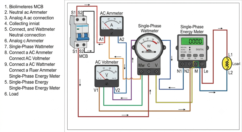
A typical calibration setup consists of a controlled AC source, a meter under test, a reference energy meter or precision power analyzer, and a pulse-counting or energy-measurement system.
The voltage and current supplied to the meter must be controlled so that both the meter under test and the reference instrument measure the same electrical conditions.
For a direct-connected meter, the current path must be connected according to the meter’s wiring diagram. For a meter connected through an instrument transformer, the applicable ratio and phase-angle corrections must be considered.
A phantom-load arrangement is often used in calibration laboratories because it permits independent control of voltage and current without dissipating the full load power in an external load bank.
Important: The exact wiring depends on the test bench and meter design. Follow the manufacturer’s connection diagram rather than relying on a generic connection arrangement.
Step-by-Step Single Phase Energy Meter Calibration Procedure
Step 1: Perform the No-Load Test
Apply the specified rated voltage to the meter while ensuring that the current is zero or within the no-load test conditions specified by the applicable standard.
Observe the energy register, pulse output, or rotating disc.
The meter should not register energy beyond the limits permitted by the relevant no-load test requirements. Unexpected registration may indicate creeping, leakage current, wiring problems, or an internal fault.
Step 2: Perform the Starting Test
The starting test checks whether the meter begins registering energy at the specified starting current.
Apply the voltage and a small current prescribed for the meter’s rated values and accuracy class. Observe the pulse output or rotating disc for the required test duration.
The meter should start registering in accordance with the applicable requirements.
Step 3: Perform the Light-Load Test
Apply a low current at the specified power factor. This test checks meter accuracy under light-load conditions.
The test current must be selected from the applicable standard or meter test specification. Do not assume that 5% of rated current is suitable for every meter.
Record the reference energy and the energy indicated by the meter under test.
Step 4: Perform the Intermediate-Load Test
Increase the current to an intermediate test point, such as approximately 50% of the relevant rated current, where appropriate for the specified test procedure.
Maintain the required voltage, frequency, and power factor.
Compare the energy indicated by the meter with the reference value. This test helps determine whether the meter maintains accuracy as the load increases.
Step 5: Perform the Rated-Load Test
Apply the specified rated or basic current and the required power factor. A maximum-current test may also be necessary if it is included in the applicable procedure.
Allow the readings to stabilize and collect enough pulses or energy data to obtain a meaningful result.
Record the reference energy, meter energy, test current, voltage, power factor, and test duration.
Step 6: Perform the Power-Factor Test
Test the meter at the required non-unity power factor, commonly a lagging power factor for suitable inductive-load tests.
This test evaluates the meter’s performance when voltage and current are not in phase.
The test points and acceptable errors depend on the meter type and accuracy class. For meters designed to measure energy under specified phase-angle conditions, follow the manufacturer’s test procedure and the relevant standard.
Step 7: Measure the Energy Reading
The method depends on the type of energy meter.
Electronic energy meter: Count the LED pulses or use the meter’s pulse output or energy register.
Electromechanical energy meter: Count the disc revolutions and use the meter constant, usually expressed in revolutions per kWh.
For an electronic meter with a pulse constant of (K) pulses/kWh, the energy represented by (N) pulses is:
where:
- = energy registered by the meter
- = number of pulses counted
- = pulse constant in pulses/kWh
For a meter with a disc constant of Wh/revolution, the energy represented by (N) revolutions is:
Always use the actual constant printed on the meter or specified in its documentation.
Step 8: Calculate the Percentage Error
The percentage error indicates how much the meter reading differs from the reference value.
Where:
- = energy measured by the meter under test
- = energy measured by the reference standard
A positive result indicates that the meter registers more energy than the reference. A negative result indicates that it registers less energy.
Example:
Suppose the meter under test records 1.020 kWh, while the reference meter records 1.000 kWh.
The meter has a positive error of 2% at this test point. Whether it passes or fails depends on its specified accuracy class and the applicable test requirements.
Step 9: Compare the Error with the Permissible Limit
Compare the measured error at each test point with the applicable maximum permissible error.
Do not assume that every single-phase meter must remain within ±1% or ±2%. Permissible error varies according to the meter’s accuracy class, current range, power factor, and applicable requirements.
Prepare a test table containing the test conditions, reference energy, meter energy, calculated error, permissible limit, and pass/fail result.
Step 10: Adjust the Meter, If Permitted
If the meter fails the accuracy test, investigate the cause before making adjustments.
For electronic meters, calibration may involve authorized changes to gain, phase compensation, or offset parameters through manufacturer-approved software or calibration registers.
For electromechanical meters, adjustments may involve the braking magnet, phase compensation, or friction compensation, depending on the design.
Adjustment should only be performed by authorized personnel using the manufacturer’s procedure. Sealed revenue meters must not be opened or adjusted without the required authorization.
Step 11: Repeat the Calibration Tests
After adjustment or repair, repeat the required tests at all relevant load and power-factor points.
Confirm that the meter meets the applicable accuracy limits throughout the specified operating range, not merely at one load point.
Record the final results and identify the meter as compliant or non-compliant according to the laboratory’s acceptance procedure.
Advanced Calibration Using a Precision Power Analyzer
A precision power analyzer can provide more detailed information than a basic pulse-counting arrangement.
Depending on its capabilities, the analyzer can be used to assess:
- Active energy measurement
- Reactive energy and apparent energy, where supported
- Voltage, current, power, and power factor
- Phase-angle errors
- Harmonic distortion and waveform quality
- Measurement stability during extended tests
Harmonic and distorted-waveform testing should only be performed when required by the meter specification or applicable test standard. It is not a substitute for the prescribed basic accuracy tests.
Energy Meter Calibration Report
After completing the tests, prepare a calibration report containing the following information:
| Parameter | Details to Record |
| Meter identification | Manufacturer, model, and serial number |
| Meter rating | Voltage, frequency, current, and accuracy class |
| Meter constant | Pulses/kWh or Wh/revolution |
| Reference equipment | Instrument identification and calibration status |
| Test conditions | Voltage, current, frequency, and power factor |
| Test results | Reference energy, meter energy, and percentage error |
| Acceptance criteria | Applicable standard and permissible error |
| Final status | Pass, fail, or adjustment required |
| Traceability | Reference standard and calibration certificate details |
| Authorization | Test date and responsible personnel |
Maintain the report according to the laboratory’s quality system and applicable regulatory requirements. Establish the recalibration interval based on regulations, manufacturer guidance, usage conditions, and the meter’s performance history.
Safety Precautions During Energy Meter Calibration
Electrical energy meter testing can involve hazardous voltages and currents. Follow these precautions:
- Isolate the supply before connecting or disconnecting the meter.
- Verify the absence of voltage before handling terminals.
- Use test leads and accessories rated for the circuit.
- Confirm terminal connections and polarity before energizing the setup.
- Avoid short circuits and accidental open circuits in instrument-transformer secondary circuits.
- Use appropriate barriers and protective equipment.
- Do not bypass meter seals or change calibration settings without authorization.
- De-energize the test setup before making wiring changes.
Conclusion
Single phase energy meter calibration is essential for verifying the accuracy and reliability of electrical energy measurements. The procedure involves inspecting the meter, checking no-load and starting performance, testing at multiple load and power-factor points, calculating percentage error, and comparing the results with the applicable accuracy limits.
A calibrated reference standard, a suitable test bench, correct test conditions, and proper documentation are necessary for reliable results. Following the relevant IEC, ANSI, and applicable national requirements helps ensure dependable energy measurement for billing, energy auditing, and electrical system monitoring.
Read Next: