A three phase energy meter is used to measure the energy consumption of three phase electrical systems, recording power in kilowatt-hours (kWh) or megawatt-hours (MWh). It is essential for industries, commercial buildings, and residential complexes supplied with three phase power. The connection of a three phase energy meter ensures accurate measurement across all three phases, even when loads are unbalanced, which is particularly important in systems where single-phase and three-phase loads are mixed.
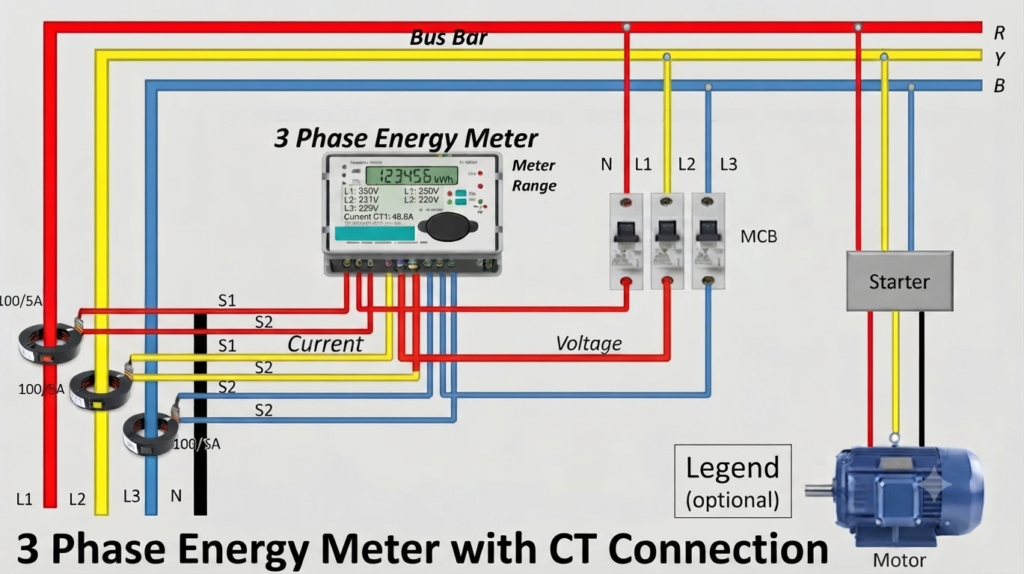
The three phase energy meter connection diagram illustrates the proper wiring setup, making it easier to understand how 3-wire and 4-wire systems are connected for precise energy calculation.
Working Principle of a Three Phase Energy Meter
The working principle of a three phase energy meter is based on electromagnetic induction. Both current coils (connected in series with the load) and voltage coils (connected across the supply) play a role. When current flows through the coils in all three phases, and voltage is applied across the potential coils, their magnetic fields interact to produce a rotating magnetic field.
- In electromechanical meters, this rotating field induces eddy currents in a lightweight aluminum disc. The disc rotates at a speed proportional to the power consumption, and the number of revolutions is counted and displayed as energy used (in kWh).
- In electronic (digital) meters, sensors and microcontrollers take both current and voltage signals from all three phases, multiply them to calculate power, and integrate over time to compute total energy. These meters provide higher accuracy, digital displays, and often remote monitoring.
Three Phase Energy Meter Connection Diagram
Understanding how a three-phase energy meter is connected is essential for accurate measurement of power and energy in industrial, commercial, and residential setups. These meters can be connected in two main ways—3-wire and 4-wire—depending on whether the system uses only phase lines or includes a neutral conductor. Below are the two connection types explained clearly.
Three Phase 3 Wire Energy Meter Connection
A three phase 3-wire energy meter is commonly used in three phase systems without a neutral wire. It measures the power and energy consumption in systems where only the three line conductors (R, Y, B) are available. This type of connection is widely used in industrial and commercial applications with balanced or delta-connected loads.
The connection diagram of a three phase 3-wire energy meter is shown in the image below.
Three Phase 4 Wire Energy Meter Connection
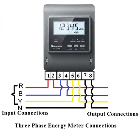
A three phase 4-wire energy meter is widely used in distribution systems where loads are connected in star (wye) configuration with a neutral conductor. This type of meter is ideal for measuring energy consumption in residential complexes, commercial buildings, and industries where single-phase and three-phase loads are mixed.
In such systems, if the load on the three phases is not perfectly balanced, the difference in current between the phases flows through the neutral conductor. This current unbalance is naturally carried by the neutral and must be measured to ensure accurate energy calculation.
The connection diagram of a three phase 4-wire energy meter is shown in the image below.
Single-Phase Energy Meter Connection with CT
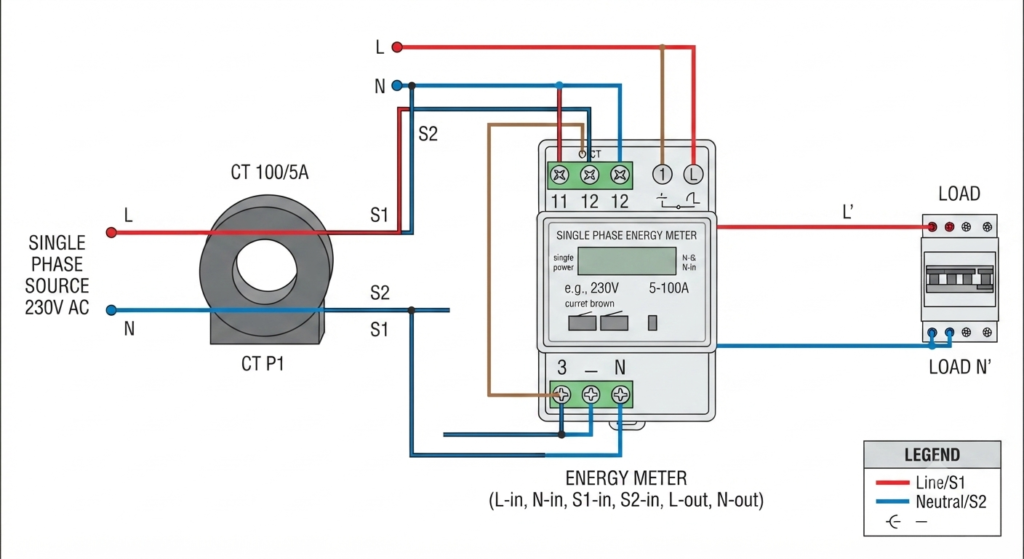
A single-phase energy meter with a CT is used when the load current is too high for the meter to measure directly. The CT steps down the current to a safe level, allowing the meter to measure energy accurately without being overloaded. This setup is commonly used in industries, large commercial buildings, or high-current single-phase circuits.
Parameters of a Three Phase Digital Energy Meter
| Parameter | Details |
| Voltage | Line-to-Line: RY, YB, RB Line-to-Neutral: RN, YN, BN |
| Current | Phase currents: R, Y, B Neutral current (N) |
| Phase-wise Load (%) | Load on each phase shown as % of full load capacity |
| Unbalance Load (%) | Voltage unbalance % Current unbalance % |
| Power Factor (pf) | Phase-wise pf: pf1, pf2, pf3 |
| Power Measurement | Apparent Power (VA), Active Power (W), Reactive Power (VAR) Per phase and total |
| Energy Measurement | Apparent Energy (VAh), Active Energy (Wh), Reactive Energy (+VARh) |
| CT Polarity Check | Detects polarity errors in current transformer connections |
Types of Three Phase Energy Meters
Three phase energy meters can be broadly classified into the following types:
- Electromechanical (Analog) Meters
- Traditional design with a rotating aluminum disc.
- Works on the induction principle.
- Less accurate compared to modern meters.
- Electronic (Digital) Meters
- Use microprocessors and sensors for energy measurement.
- Provide real-time data, remote monitoring, and accuracy.
- Commonly used in smart grid systems.
- Prepaid Energy Meters
- Consumers pay in advance for the energy they use.
- Reduces billing issues and improves revenue collection for utilities.
Applications of Three Phase Energy Meters
Three phase energy meters are widely used in:
- Industrial plants (heavy machinery, motors, compressors).
- Commercial complexes (malls, hospitals, hotels).
- Residential societies with high load consumption.
- Utility companies for billing and monitoring purposes.
Advantages of Three Phase Energy Meters
- Accurate measurement of energy in large power systems.
- Suitable for both balanced and unbalanced loads.
- Long service life and reliability.
- Digital meters offer remote monitoring and smart grid compatibility.
Conclusion
A three phase energy meter is a vital device for monitoring and billing in modern power systems. Whether electromechanical or digital, these meters ensure accurate energy measurement for industries, businesses, and high-load residential areas. With the shift toward smart grid technology, digital and prepaid three phase meters are becoming more common, improving efficiency and transparency in energy management.
Read Next:
- Calculation of Multiplication Factor of Energy Meters
- Clamp Meter Working Principle, Diagram & Uses
- Electrical Energy Sources – Types, Examples, and How Electricity is Produced
- CT Full Form in Electrical | Current Transformer Connection, Diagram
- Difference Between Indicating and Recording Instruments