The Galvanometer Half Deflection Method is an experimental technique used to determine the internal resistance and figure of merit of a galvanometer. It is based on the principle of current division, in which a known shunt resistance is connected in parallel with the galvanometer to reduce the current flowing through its coil.
In this experiment, the initial deflection of the galvanometer is first recorded by passing a small current through it. A shunt resistance is then connected across the galvanometer and adjusted until the pointer deflection becomes half of its initial value.
By recording the series resistance and the shunt resistance corresponding to half deflection, the galvanometer resistance can be calculated. The figure of merit is subsequently determined using the cell’s EMF, total circuit resistance, and initial deflection.
This method is commonly used in physics and electrical laboratory experiments to evaluate the electrical characteristics and sensitivity of a galvanometer.
Principle of Galvanometer Half Deflection Method
The half deflection method is based on the relationship between the current flowing through a galvanometer and its pointer deflection.
For a moving-coil galvanometer operating within its linear range, the deflection is directly proportional to the current flowing through the coil.
Therefore,
When a galvanometer of resistance G is connected in series with a resistance R and a battery of EMF E, a current flows through the circuit and produces an initial deflection θ.
A variable shunt resistance S is then connected in parallel with the galvanometer. The shunt provides an alternative path for current, reducing the current through the galvanometer coil.
The shunt resistance is adjusted until the galvanometer deflection becomes half of its original value.
Thus,
Since deflection is proportional to current, the current through the galvanometer also becomes half of its initial value.
Using this condition and the current division principle, the galvanometer resistance can be determined.
Galvanometer Half Deflection Experiment
Aim of the Experiment
The main objectives of the galvanometer half deflection experiment are:
- To determine the internal resistance of a galvanometer using the half deflection method.
- To calculate the figure of merit of the galvanometer.
- To understand how a shunt resistance controls the current flowing through a galvanometer.
Apparatus Required
The following apparatus is required to perform the experiment:
- Moving-coil galvanometer
- Battery or electric cells of known EMF
- Resistance boxes for series and shunt resistance
- Plug keys or switches
- Connecting wires
- Rheostat, if required
Circuit Diagram and Experimental Arrangement
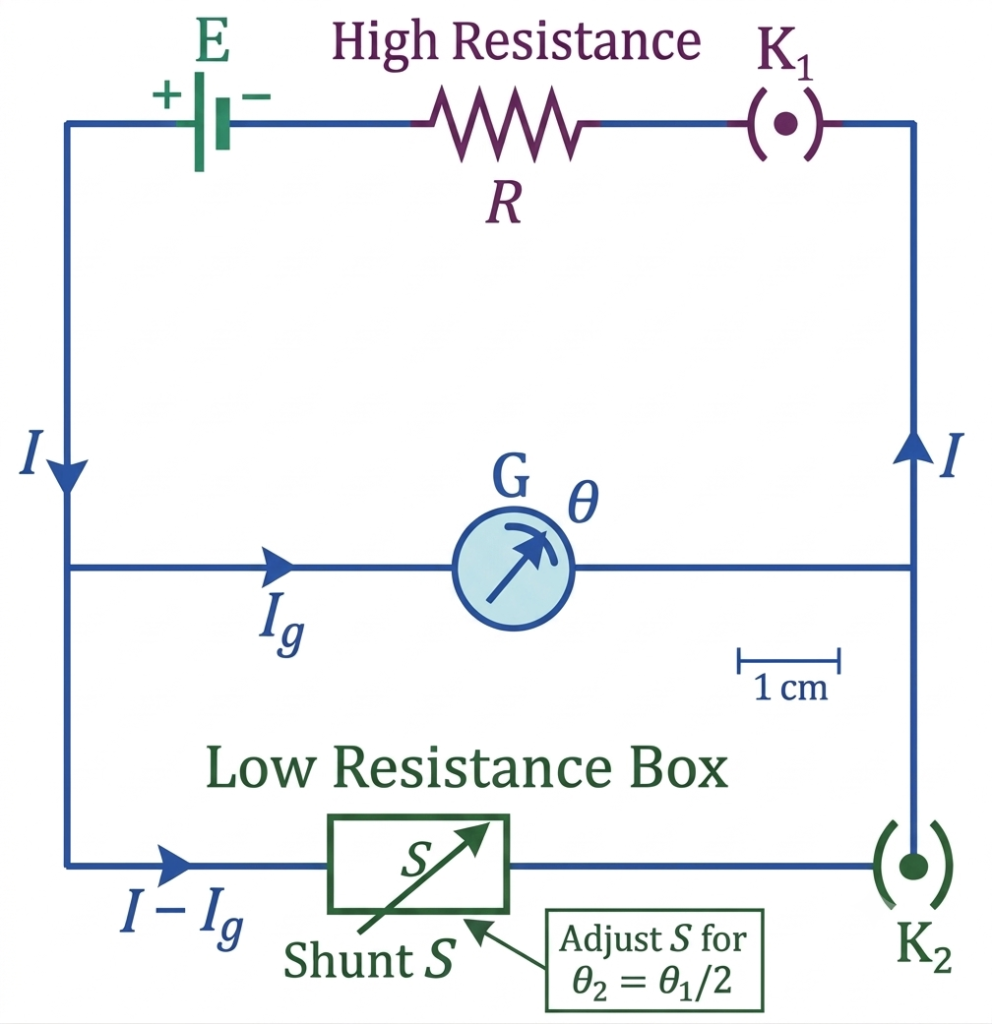
The experimental circuit consists of a battery, a key, a series resistance box, and a galvanometer connected in series. A separate shunt resistance box is connected in parallel with the galvanometer.
Initially, the shunt circuit remains open. After recording the initial deflection, the shunt is connected across the galvanometer and adjusted to obtain half deflection.
The series resistance limits the current flowing through the galvanometer, while the shunt controls the current distribution between the galvanometer and the parallel resistance.
Formula for Galvanometer Resistance by Half Deflection Method
The resistance of a galvanometer can be calculated using the following expression:
Where:
- G = Internal resistance of the galvanometer (Ω)
- R = Series resistance connected in the circuit (Ω)
- S = Shunt resistance required to produce half deflection (Ω)
Derivation of Galvanometer Resistance Formula- ByHalf Deflection Method
Consider a galvanometer having resistance G connected in series with a resistance R and a battery of EMF E.
When the shunt resistance is disconnected, the current flowing through the galvanometer is:
Let the corresponding galvanometer deflection be θ.
According to the principle of a moving-coil galvanometer:
When a shunt resistance S is connected in parallel with the galvanometer, the deflection becomes half of its initial value.
Therefore, the new galvanometer current is:
The potential difference across the galvanometer and shunt is the same because they are connected in parallel.
Hence,
Since the total current after introducing the shunt is I:
Substituting the equal-current condition obtained from the half-deflection relationship:
and
Therefore,
This gives the approximate result:
However, introducing the shunt also changes the equivalent resistance of the parallel combination and consequently increases the total circuit current. Therefore, the original current and the current after shunting are not exactly equal.
Taking this change into account, the exact relationship is:
This is the formula used to calculate the galvanometer resistance in the half deflection experiment.
Experimental Procedure
Follow these steps to determine the resistance and figure of merit of a galvanometer.
- Connect the battery, plug key, series resistance box, and galvanometer in series according to the experimental circuit diagram.
- Keep the shunt resistance disconnected initially.
- Select a sufficiently high value of series resistance R to protect the galvanometer from excessive current.
- Close the key and observe the initial deflection θ on the galvanometer scale.
- Record the initial deflection and open the key.
- Connect the shunt resistance box in parallel with the galvanometer.
- Close the key and gradually adjust the shunt resistance until the galvanometer deflection becomes exactly half of its initial value.
- Record the corresponding shunt resistance S.
- Open the key and repeat the experiment using different values of series resistance.
- Calculate the galvanometer resistance using the half deflection formula.
- Determine the figure of merit using the initial deflection and calculated galvanometer resistance.
- Calculate the average values of galvanometer resistance and figure of merit from the observations.
Observation Table
The following observations are recorded during the experiment.
EMF of the cell: E = ______ V
| S. No. | Series resistance R (Ω) | Initial deflection θ (divisions) | Shunt resistance S (Ω) | Galvanometer resistance G (Ω) | Figure of merit k (A/div) |
| 1 | |||||
| 2 | |||||
| 3 | |||||
| 4 | |||||
| Average |
Calculation of Galvanometer Resistance
For each observation, calculate the galvanometer resistance using:
Calculation of Figure of Merit
The figure of merit of a galvanometer is defined as the amount of current required to produce a deflection of one division on its scale.
The figure of merit is calculated using:
The average values of G and k are obtained from the experimental observations.
Example: Sample Calculation( Galvanometer Half Deflection Method)
Suppose the following experimental values are obtained:
- EMF of cell, E = 2 V
- Series resistance, R = 1000 Ω
- Initial deflection, θ = 40 divisions
- Shunt resistance at half deflection, S = 100 Ω
Step 1: Calculate galvanometer resistance
Substituting the values:
Step 2: Calculate the figure of merit
Substituting the values:
Therefore,
The galvanometer resistance is approximately 111.11 Ω, and its figure of merit is 45 µA per division.
Precautions During the Experiment
The following precautions should be observed to obtain reliable results:
- Always use a sufficiently high series resistance to protect the galvanometer from excessive current.
- Ensure that all electrical connections are tight and properly insulated.
- Connect the shunt resistance in parallel with the galvanometer.
- Check the galvanometer zero setting before starting the experiment.
- Adjust the shunt resistance carefully to obtain exactly half of the initial deflection.
- Keep the key open when readings are not being taken to prevent unnecessary current flow and heating.
- Avoid parallax errors while observing the galvanometer scale.
- Use a suitable range of series resistance to obtain clear and measurable deflections.
- Ensure that the cell EMF remains stable throughout the experiment.
- Repeat the readings and use average values to reduce experimental errors.
Sources of Experimental Error
The accuracy of the half deflection method can be affected by several factors:
- Fluctuations in the battery EMF.
- Contact resistance in connecting wires and keys.
- Inaccurate adjustment of the shunt resistance.
- Errors in reading the galvanometer scale.
- Temperature changes affecting the resistance of the galvanometer coil.
- Mechanical friction or an incorrect zero setting of the galvanometer.
Careful connections, suitable resistance selection, and repeated observations help minimize these errors.
Applications of the Half Deflection Method
The half deflection method is useful in electrical and physics laboratories for:
- Determining the internal resistance of a galvanometer.
- Calculating the figure of merit of a moving-coil galvanometer.
- Evaluating the current sensitivity of a galvanometer.
- Studying current division in parallel electrical circuits.
- Understanding the relationship between galvanometer current and pointer deflection.
Conclusion
The galvanometer half deflection method provides a practical way to determine the internal resistance and figure of merit of a galvanometer. In this experiment, a shunt resistance is connected in parallel with the galvanometer and adjusted until its initial deflection is reduced by half.
The measured series and shunt resistances are then used to calculate the galvanometer resistance using (G=RS/(R-S)). The figure of merit is determined from the cell EMF, total series resistance, and initial deflection. These two parameters help evaluate the electrical characteristics and sensitivity of a galvanometer.
Read Next:
- Conversion of Galvanometer into Voltmeter: Formula, Derivation and Working
- Conversion of Galvanometer into Ammeter – Formula, Circuit Diagram and Derivation
- Applications of Galvanometer
- Galvanometer: Definition, Working Principle, Construction and Working
- Sensitivity of Galvanometer: Formula, Types, Factors and Explanation
- Figure of Merit of a Galvanometer: Formula, Experiment and Calculation
- Galvanometer Resistance: Formula, Calculation and Measurement
- Moving Coil Galvanometer: Principle, Construction, Working, Diagram, Formula Derivation
- Galvanometer Constant: Formula, Derivation, Definition and Significance
- Galvanometer and Direction of Current