A frequency meter is an important electrical measuring instrument used to determine the frequency of an electrical signal. It helps engineers and technicians monitor the operating frequency of generators, motors, power supplies and electrical distribution systems.
Frequency plays a vital role in the performance of electrical equipment. In many countries, the standard AC supply frequency is 50 Hz, while some countries use 60 Hz. A significant change in supply frequency can affect motor speed, generator performance and the operation of connected equipment.
For example, if a generator designed to operate at 50 Hz produces an output frequency of 45 Hz, connected motors may run at lower speeds and industrial processes may be affected. A frequency meter helps identify such variations so that corrective action can be taken.
Frequency meters are available in analog and digital designs. Depending on their construction and operating principle, they may use mechanical vibration, electrical resonance or electronic pulse-counting techniques.
This article explains the frequency meter working principle, different types, main components, applications, advantages, disadvantages and important factors to consider when selecting one.
What Is a Frequency Meter?
A frequency meter is an electrical measuring instrument used to measure the frequency of a periodic electrical signal. It indicates how many complete cycles occur in one second. The measured value is expressed in Hertz (Hz).
One Hertz represents one complete cycle per second.
For example:
- 1 Hz means one complete cycle per second.
- 50 Hz means 50 complete cycles per second.
- 60 Hz means 60 complete cycles per second.
- 1 kHz means 1,000 cycles per second.
Frequency meters are commonly used to measure AC supply frequency and the frequency of electronic signals. They are installed in electrical panels, substations, generator control panels, laboratories and industrial testing systems.
Practical example: A frequency meter connected to a 50 Hz generator indicates whether its output frequency is close to the rated value. If the frequency falls or rises beyond the permitted operating range, the operator can investigate the cause.
Frequency Meter Working Principle
The working principle of a frequency meter depends on its design. In a digital frequency meter, the input signal is converted into pulses, which are counted during a precisely controlled time interval. The number of pulses counted per second gives the frequency of the signal.
Analog frequency meters use different operating principles. Some respond to the frequency-dependent impedance of electrical circuits, while others use mechanical or electrical resonance.
How Does a Digital Frequency Meter Work?
A digital frequency meter generally performs the following operations:
- Input signal: The unknown electrical signal is applied to the input circuit.
- Signal conditioning: The input circuit amplifies or adjusts the signal to a suitable level.
- Pulse generation: A trigger circuit converts the input waveform into clean electrical pulses.
- Pulse counting: An electronic counter counts the pulses during a known time interval.
- Frequency calculation: The instrument determines the frequency from the pulse count and measurement time.
- Display: The measured frequency is displayed in Hz, kHz or MHz.
The frequency is calculated using:
Where:
- = Frequency in Hz
- = Number of cycles or pulses counted
- = Measurement time in seconds
Example:
Suppose a digital frequency meter counts 5,000 pulses during a measurement interval of 1 second.
Therefore, the measured frequency is 5 kHz.
How Does an Analog Frequency Meter Work?
An analog frequency meter indicates the frequency through the movement of a pointer over a calibrated scale. Its internal mechanism responds to changes in the input frequency.
Depending on the instrument design, it may use vibrating reeds, moving-iron mechanisms, electrodynamic principles or electrical resonance.
The pointer position or the reed showing maximum vibration indicates the corresponding frequency. Analog frequency meters are particularly useful for continuous monitoring of AC supply frequency in electrical panels and generator systems.
Types of Frequency Meter
Frequency meters are classified according to their construction and operating principle. The commonly used types include analog frequency meters, digital frequency meters, vibrating reed frequency meters, resonance frequency meters and electronic frequency counters.
Analog Frequency Meter
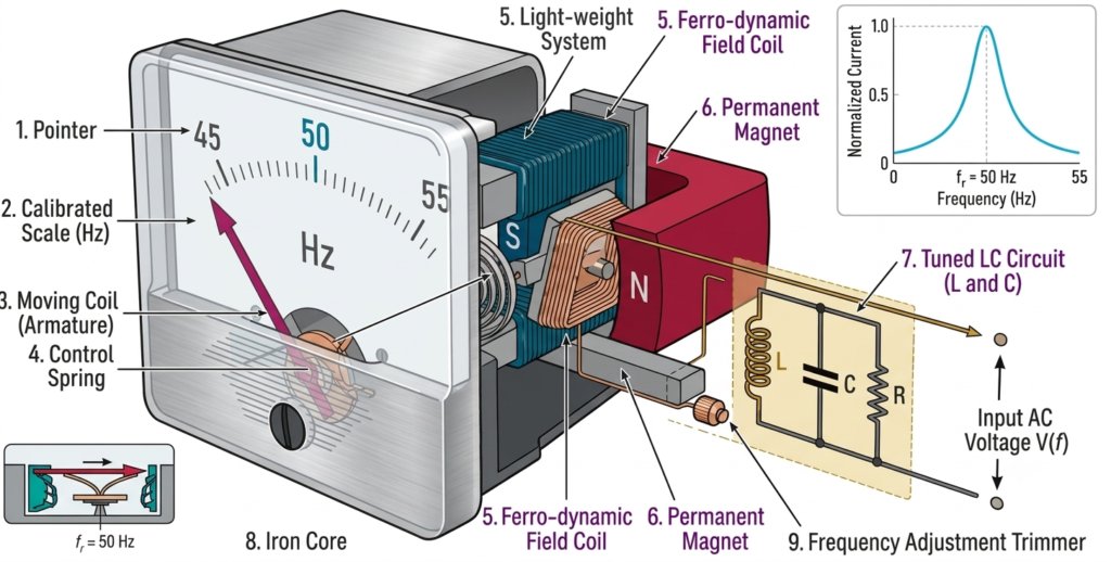
An analog frequency meter measures the frequency of an AC electrical supply and displays the result through a moving pointer and calibrated scale.
Depending on its design, it may use a moving-iron or electrodynamic ratio mechanism. In a ratio-type instrument, two electrical quantities respond differently to changes in frequency. The resulting torque moves the pointer to the corresponding scale position.
Analog frequency meters are commonly installed in generator panels, substations, electrical switchboards and industrial control panels.
Features:
- Uses a pointer and graduated scale.
- Provides continuous visual indication.
- Suitable for monitoring frequency variations.
- Simple construction and operation.
- Does not require a numerical digital display.
Applications:
- Generator control panels.
- Power distribution systems.
- Industrial electrical panels.
- Substations and power stations.
Digital Frequency Meter
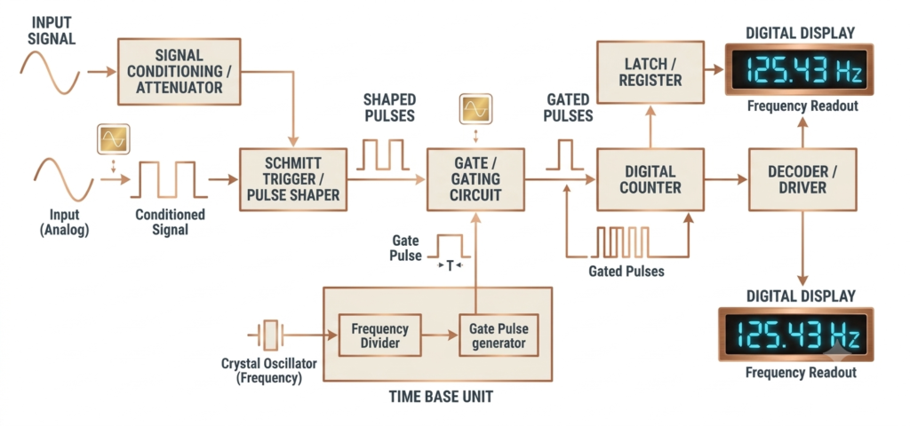
A digital frequency meter is an electronic instrument that measures the frequency of an electrical or electronic signal and displays the result numerically on an LCD or LED screen.
It generally works by converting the input signal into pulses and counting them during a precisely defined time interval. A stable time-base circuit controls the measurement period, allowing the instrument to calculate frequency accurately.
Digital frequency meters are widely used in electrical engineering, electronic testing, communication systems, industrial automation and laboratories.
Features:
- Numerical frequency display.
- High measurement accuracy, depending on the instrument.
- Fast and convenient reading.
- Wide measurement range in suitable models.
- Some models also measure period, pulse width and duty cycle.
Applications:
- Testing electronic circuits.
- Measuring oscillator frequency.
- Generator frequency monitoring.
- Communication equipment testing.
- Industrial automation systems.
Vibrating Reed Frequency Meter
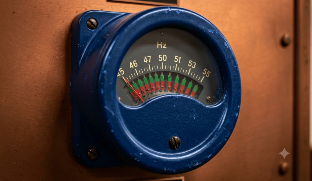
A vibrating reed frequency meter is an analog instrument that works on the principle of mechanical resonance.
It consists of several thin metal reeds, each adjusted to vibrate at a particular natural frequency. These reeds are positioned near an electromagnet connected to the AC supply.
When the supply is applied, the electromagnet produces an alternating magnetic field. The reed whose natural frequency matches the supply frequency vibrates with the greatest amplitude due to resonance.
The frequency is identified by observing the reed that vibrates most strongly. Each reed has a frequency value marked beside it.
For example, a vibrating reed frequency meter may have reeds calibrated over a range around the standard 50 Hz supply frequency.
Features:
- Works on mechanical resonance.
- Contains multiple frequency-tuned metal reeds.
- The reed with maximum vibration indicates the frequency.
- Simple and rugged construction.
- Suitable for a limited frequency range.
Applications:
- Generator panels.
- Power stations.
- Electrical switchboards.
- Substations.
- AC supply frequency monitoring.
Resonance Frequency Meter
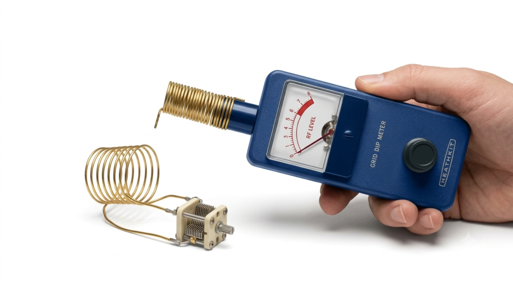
A resonance frequency meter measures frequency using the electrical resonance principle. It generally consists of an inductor and capacitor connected to form a tunable LC circuit.
The resonant frequency of an ideal LC circuit is given by:
Where:
- = Resonant frequency in Hz
- = Inductance in henry
- = Capacitance in farad
During measurement, the inductance or capacitance is adjusted until the circuit reaches resonance with the unknown input signal. At resonance, the inductive reactance and capacitive reactance are equal in magnitude.
The resonant condition produces a noticeable response, such as maximum current in a series resonant circuit. The corresponding calibrated scale indicates the frequency.
Features:
- Operates on electrical resonance.
- Uses an LC resonant circuit.
- Requires tuning to identify the resonant point.
- Suitable for radio-frequency and electronic measurements.
Applications:
- RF circuit testing.
- Oscillator measurements.
- Communication equipment.
- Electronic laboratories.
- Educational experiments involving resonance.
Electronic Frequency Counter
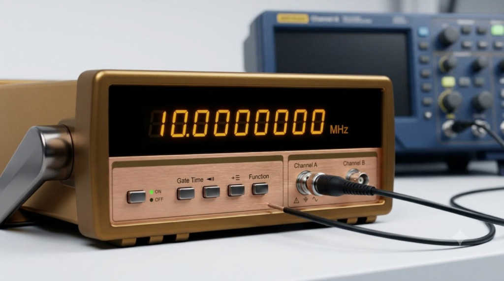
An electronic frequency counter is a digital instrument designed to measure the frequency of electrical and electronic signals by counting their cycles over a known time interval.
The input signal is first conditioned into suitable pulses. A high-speed counter then counts these pulses while a crystal-controlled time base determines the measurement interval. The resulting count is processed and shown on a digital display.
Electronic frequency counters are commonly used for precise measurements in laboratories, communication systems and electronic equipment testing.
Features:
- Uses electronic pulse-counting circuits.
- Provides numerical frequency readings.
- Uses a stable time base.
- Can measure a wide frequency range, depending on the model.
- May include period, time interval and pulse-counting functions.
Applications:
- Testing signal generators.
- Measuring oscillator frequency.
- RF equipment testing.
- Communication systems.
- Electronic circuit development and calibration.
Main Components of a Frequency Meter
The components of a frequency meter depend on its operating principle. A digital frequency meter generally contains the following sections.
1. Input Terminal
The input terminal receives the electrical signal from the circuit or equipment being tested. It transfers the signal to the internal measurement circuit.
Its design must be suitable for the expected input voltage, frequency range and signal type.
Functions:
- Receives the input signal.
- Provides connection to the measuring circuit.
- Supports reliable signal transmission.
- Helps ensure proper input interfacing.
2. Signal Conditioning Circuit
The signal conditioning circuit prepares the incoming signal for measurement. It may amplify weak signals, attenuate high-level signals and reduce unwanted noise.
The purpose is to provide a suitable waveform for the pulse-generation or measurement circuit.
Functions:
- Adjusts the input signal level.
- Improves signal quality.
- Reduces unwanted interference.
- Prepares the waveform for accurate measurement.
3. Trigger Circuit
A trigger circuit, such as a Schmitt trigger, converts the conditioned input waveform into clean digital pulses.
These pulses provide distinct transitions that can be counted by the electronic counter.
Functions:
- Converts the input waveform into pulses.
- Provides well-defined switching transitions.
- Reduces the effect of small signal variations near the switching threshold.
- Supplies pulses to the counting circuit.
4. Time-Base Generator
The time-base generator provides a stable timing reference for frequency measurement. It commonly uses a crystal-controlled oscillator to generate accurate timing signals.
These signals determine the interval during which the counter receives input pulses.
Functions:
- Generates accurate timing signals.
- Controls the measurement interval.
- Determines the counting period.
- Supports measurement accuracy.
5. Electronic Counter
The electronic counter counts the pulses received from the input circuit during the selected measurement interval.
The total count is used to calculate the frequency of the input signal.
Functions:
- Counts incoming pulses.
- Stores the pulse count temporarily.
- Provides data for frequency calculation.
- Supports digital frequency measurement.
6. Display Unit
The display unit shows the measured frequency in numerical form. Depending on the meter design, it may use an LCD, LED or another digital display.
Analog frequency meters use a pointer and calibrated scale instead.
Functions:
- Displays the measured frequency.
- Shows the reading in suitable units.
- Allows easy observation of frequency changes.
7. Power Supply
The power supply provides the energy required to operate the meter’s internal circuits. Depending on the model, it may use an external DC supply, battery or AC mains supply.
Advantages of Frequency Meter
A frequency meter provides several benefits in electrical measurement, testing and monitoring.
- Accurate measurement: Digital frequency meters can provide precise readings when used within their specified operating range.
- Easy monitoring: It helps operators observe changes in supply or signal frequency.
- Improved system reliability: Frequency monitoring helps identify abnormal operating conditions.
- Equipment protection: Detecting frequency deviations can help prevent problems in equipment designed for a specific frequency range.
- Wide applications: Frequency meters are used in power systems, industrial plants, laboratories and electronic circuits.
- Continuous monitoring: Panel-mounted frequency meters can provide continuous indication of electrical supply frequency.
Disadvantages and Limitations of Frequency Meter
Although frequency meters are useful measuring instruments, they have certain limitations.
- Limited measurement range: Every frequency meter has a specified operating range. Signals outside this range may not be measured correctly.
- Input signal dependency: Noise, distortion and weak input signals can affect the measurement.
- Calibration requirements: Periodic calibration may be necessary to maintain measurement accuracy.
- Analog reading errors: Pointer-based instruments may introduce reading errors due to parallax and limited scale resolution.
- Counter speed limitation: Direct-counting digital meters have a maximum input frequency determined by their electronic circuits.
- Power requirement: Most digital frequency meters require a suitable power supply to operate.
Applications of Frequency Meter
Frequency meters are used in several electrical, electronic and industrial applications. They help maintain the correct operating frequency and support equipment testing and troubleshooting.
1. Power Plants
Frequency meters are installed in power plant control panels to monitor the frequency of generated electricity.
Applications:
- Monitoring generator output frequency.
- Observing frequency variations.
- Supporting generator operation.
- Monitoring electrical system stability.
2. Generators
A frequency meter helps operators verify whether a generator is producing electricity at the required frequency.
Applications:
- Checking generator output frequency.
- Monitoring frequency during operation.
- Supporting generator maintenance.
- Identifying abnormal frequency variations.
Since generator frequency is related to rotational speed and the number of poles, frequency measurement also provides useful information about generator operating conditions.
3. Industrial Machines and Motors
Industrial equipment often requires a suitable supply frequency for proper operation. Frequency meters help monitor the electrical supply and identify unwanted variations.
Applications:
- Monitoring AC supply frequency.
- Checking electrical supply conditions for motors.
- Supporting industrial equipment maintenance.
- Identifying frequency-related operating problems.
4. Electrical Substations
Frequency meters are used in substations to monitor the frequency of the electrical power system.
Applications:
- Monitoring grid frequency.
- Observing supply variations.
- Supporting power system operation.
- Providing frequency indication to operators.
5. Laboratories
In electrical and electronic laboratories, frequency meters are used to measure signals generated by testing equipment and electronic circuits.
Applications:
- Measuring oscillator frequency.
- Testing signal generators.
- Checking electronic circuit performance.
- Supporting instrument calibration and research.
6. Communication Systems
Communication equipment uses signals operating over a wide range of frequencies. Electronic frequency meters and counters help measure and verify these signals.
Applications:
- Testing radio-frequency signals.
- Checking transmitter frequency.
- Measuring oscillator output.
- Testing communication equipment.
7. UPS and Inverter Systems
Frequency meters can be used to check the output frequency of uninterruptible power supplies and inverters.
Applications:
- Monitoring UPS output frequency.
- Checking inverter performance.
- Testing backup power systems.
- Verifying output frequency against equipment requirements.
Frequency Meter vs Voltmeter
A frequency meter and a voltmeter are both electrical measuring instruments, but they measure different electrical quantities.
| Feature | Frequency Meter | Voltmeter |
| Measures | Frequency | Voltage |
| Unit | Hertz (Hz) | Volt (V) |
| Main purpose | Measures cycles per second | Measures potential difference |
| Common use | AC supply and signal monitoring | AC and DC voltage measurement |
| Display | Pointer or digital display | Pointer or digital display |
| Typical application | Generator frequency monitoring | Voltage monitoring in electrical circuits |
How to Choose the Right Frequency Meter
Selecting a suitable frequency meter depends on the signal being measured, required accuracy and operating environment. Consider the following factors before selecting an instrument.
1. Frequency Measurement Range
Check the minimum and maximum frequencies that the instrument can measure. A meter used for power system monitoring may require a narrow range around 50 Hz or 60 Hz, whereas electronic and RF testing may require a much wider range.
2. Measurement Accuracy
Select an instrument with an accuracy specification suitable for the application. Laboratory testing generally requires better accuracy than basic electrical panel monitoring.
3. Type of Frequency Meter
Choose the meter according to the measurement requirement.
- Analog frequency meter: Suitable for continuous visual monitoring of AC supply frequency.
- Digital frequency meter: Suitable for numerical readings and general electronic measurements.
- Vibrating reed frequency meter: Suitable for monitoring frequency around a specified range.
- Resonance frequency meter: Useful for measurements based on electrical resonance.
- Electronic frequency counter: Suitable for precise measurement of electronic and high-frequency signals.
4. Display and Readability
Choose a meter with a clear display that can be read easily in the intended working environment. A digital display is convenient for numerical measurements, while an analog scale provides a visual indication of frequency variation.
5. Input Signal Compatibility
Verify the acceptable input voltage, waveform type and signal level. The meter must be compatible with the electrical signal being measured.
6. Safety and Protection
For electrical installations, consider input protection, insulation and the instrument’s applicable measurement-category rating. Select equipment suitable for the voltage and installation environment.
7. Build Quality and Operating Conditions
For industrial applications, consider protection against dust, moisture, vibration and temperature variations. The instrument should be suitable for the location where it will be installed.
8. Calibration and Reliability
Check calibration requirements and the availability of calibration services. A properly calibrated frequency meter provides more dependable measurement results.
9. Additional Features
Depending on the application, useful features may include:
- Automatic range selection.
- Frequency and period measurement.
- Pulse counting.
- Data logging.
- Remote communication.
- Digital output for monitoring systems.
Common Frequency Meter Problems and Solutions
Incorrect or unstable frequency readings may result from input signal problems, wiring faults, electrical interference or instrument defects.
1. Unstable Frequency Reading
Possible causes:
- Electrical noise or interference.
- Loose input connections.
- Fluctuating input signal.
- Poor grounding or shielding.
Solutions:
- Check and tighten input connections.
- Use suitable shielded measurement cables.
- Improve signal conditioning where required.
- Verify the stability of the signal source.
2. Frequency Meter Shows No Reading
Possible causes:
- No input signal.
- Incorrect wiring.
- Instrument power supply failure.
- Faulty fuse or internal circuit.
Solutions:
- Verify that the input signal is present.
- Check the wiring and input connections.
- Confirm that the instrument has a proper power supply.
- Inspect the fuse and instrument according to the manufacturer’s instructions.
3. Incorrect Frequency Reading
Possible causes:
- Incorrect measurement range.
- Instrument calibration error.
- Distorted input waveform.
- Poor signal level.
Solutions:
- Select the correct measurement range.
- Verify the input signal quality.
- Check the instrument against a suitable reference source.
- Arrange calibration if necessary.
4. Display Flickering
Possible causes:
- Unstable power supply.
- Weak battery in portable models.
- Loose internal connections.
- Fluctuating input signal.
Solutions:
- Check the instrument supply voltage.
- Replace the battery if required.
- Inspect connections through an authorized service procedure.
- Verify the input signal.
5. Inconsistent Measurements
Possible causes:
- Electromagnetic interference.
- Damaged measurement leads.
- Poor grounding.
- Signal fluctuations.
Solutions:
- Use suitable measurement leads.
- Keep signal cables away from strong interference sources.
- Check grounding arrangements.
- Confirm that the source signal is stable.
Future Developments in Frequency Meters
Modern frequency meters are increasingly using digital processing, communication interfaces and automated monitoring features. These developments make frequency measurement more convenient and improve the integration of instruments with industrial control systems.
1. Smart Digital Frequency Meters
Microprocessor-based instruments can provide improved measurement processing, automatic range selection and additional diagnostic functions.
2. Remote Monitoring
Communication interfaces allow frequency readings to be transmitted to control rooms and monitoring systems. This reduces the need for operators to inspect every instrument locally.
3. IoT Integration
Some advanced measurement systems can transmit operating data to connected platforms. This information can support remote monitoring, historical analysis and maintenance planning.
4. PLC and SCADA Integration
Frequency measurement devices with suitable communication or output interfaces can be integrated into PLC and SCADA systems. This allows operators to monitor frequency as part of a wider industrial control system.
5. Data Logging and Analysis
Data logging makes it possible to record frequency variations over time. Engineers can examine these records to identify operating trends and investigate abnormal conditions.
Conclusion
A frequency meter is an essential electrical measuring instrument used to determine the frequency of AC supplies and periodic electrical signals. It helps engineers and technicians monitor generators, motors, power distribution systems and electronic equipment.
The frequency meter working principle varies with its design. Digital instruments generally measure frequency by counting input pulses over a known time interval, whereas analog instruments may use mechanical resonance, electrical resonance or frequency-dependent electrical mechanisms.
Common types include analog frequency meters, digital frequency meters, vibrating reed frequency meters, resonance frequency meters and electronic frequency counters. Each type is suitable for particular measurement ranges and applications.
Understanding the different types, operating principles, components and selection factors helps in choosing the right frequency meter for reliable electrical measurement and system monitoring.
Read Next:
- Wattmeter: Working Principle, Types, Advantages, and Applications
- Induction Type Wattmeter: Construction, Working Principle, Diagram, and Torque Equation
- Electrodynamometer Type Wattmeter: Construction, Working Principle
- Wattmeter Connection: Diagram and Methods Explained
- Three Wattmeter Method: Three-Phase Power Measurement
- Analog Instruments: Definition, Classification, and Working Principle
- Null Type Instrument: Principle, Example, and Key Advantages
- Types of Measuring Instruments in Electrical Engineering
- Integrating Instruments: Classifications, Advantage and Applications
- Digital Instruments: Definition, Characteristics, Construction, Advantages, and Disadvantages
- Analog Frequency Meter: Working, Types and Applications
- Digital Frequency Meter: Working Principle, Block Diagram, Construction