A moving iron instrument is an electromechanical measuring device used to measure electrical current and voltage in AC and DC circuits. It works on the principle that a soft-iron element experiences a force when placed in the magnetic field produced by a current-carrying coil.
Moving iron instruments are widely used in electrical panels, power distribution systems, laboratories, and industrial measurement applications. Their simple construction, rugged design, and ability to measure both alternating current (AC) and direct current (DC) make them suitable for general-purpose electrical measurements.
There are two main types of moving iron instruments:
- Attraction-type moving iron instrument
- Repulsion-type moving iron instrument
Both types use a fixed current-carrying coil and a movable iron element to produce pointer deflection. However, the arrangement of the iron components and the way they produce movement are different.
What Is a Moving Iron Instrument?
A moving iron instrument is an analog electrical measuring instrument in which a soft-iron piece moves under the influence of the magnetic field produced by a fixed coil.
When current flows through the coil, it creates a magnetic field that magnetizes the iron element. The resulting magnetic force produces deflecting torque and moves the pointer over a calibrated scale.
The instrument can be designed as an ammeter or a voltmeter:
- Moving iron ammeter: Measures current and is connected in series with the circuit.
- Moving iron voltmeter: Measures voltage and is connected in parallel with the circuit through a suitable high resistance.
A major advantage of a moving iron instrument is that it can operate on both AC and DC supplies.
Construction of Moving Iron Instrument
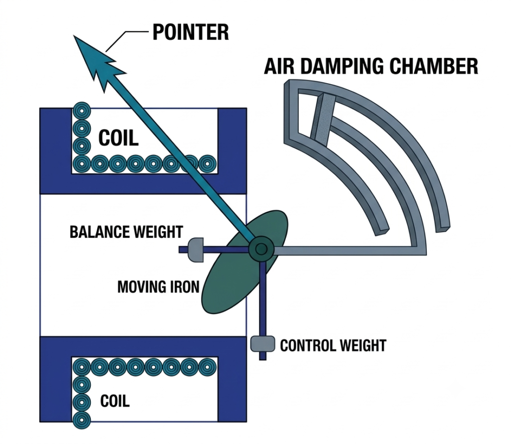
The construction of a moving iron instrument consists of several mechanical and electrical components. Their arrangement depends on whether the instrument uses the attraction or repulsion principle.
The main components are described below.
1. Fixed Coil
The fixed coil produces the magnetic field required for instrument operation.
It is generally made of insulated copper wire wound around a suitable former. The coil carries the current being measured in an ammeter. In a voltmeter, a high series resistance limits the current flowing through the coil.
2. Soft-Iron Element
The soft-iron element is the main moving magnetic component.
In an attraction-type instrument, a movable iron vane or disc is placed near the coil. In a repulsion-type instrument, two iron vanes are used, one fixed and the other movable.
The iron elements become magnetized when the coil produces a magnetic field.
3. Moving Spindle and Pointer
The movable iron element is attached to a spindle. A lightweight pointer is also connected to this spindle.
When magnetic force produces torque, the spindle rotates and moves the pointer over the calibrated scale.
4. Controlling System
The controlling system provides the opposing torque required to establish a steady pointer position.
Moving iron instruments commonly use spring control. Spiral springs produce a restoring torque that opposes the deflecting torque.
Some attraction-type instruments use gravity control, in which the weight of a control element produces the restoring torque.
5. Damping System
The damping system prevents excessive pointer oscillation and helps the pointer settle quickly at its final position.
Air-friction damping is commonly used in moving iron instruments. A vane or piston attached to the spindle moves inside an enclosed air chamber, producing a damping force.
Air damping is suitable because it does not introduce significant eddy-current damping torque into the measuring mechanism.
6. Scale and Protective Case
The pointer moves over a graduated scale that indicates the measured current or voltage.
The complete mechanism is enclosed in a protective case to protect it from dust, moisture, and mechanical damage.
Working Principle of Moving Iron Instrument
The working principle of a moving iron instrument is based on the magnetic effect of electric current.
When current flows through the fixed coil, a magnetic field is established around it. The soft-iron element placed inside or near the coil becomes magnetized.
Depending on the instrument type, the iron element is either attracted toward a stronger magnetic field or repelled by another similarly magnetized iron element.
This magnetic action produces deflecting torque, which rotates the spindle and moves the pointer.
The pointer stops when the deflecting torque becomes equal to the controlling torque.
The operating principle is the same for AC and DC supplies. In an AC circuit, the magnetic polarity changes with the direction of current, but the resulting deflecting torque remains unidirectional.
Types of Moving Iron Instruments
Moving iron instruments are classified into two types according to how the movable iron element responds to the magnetic field.
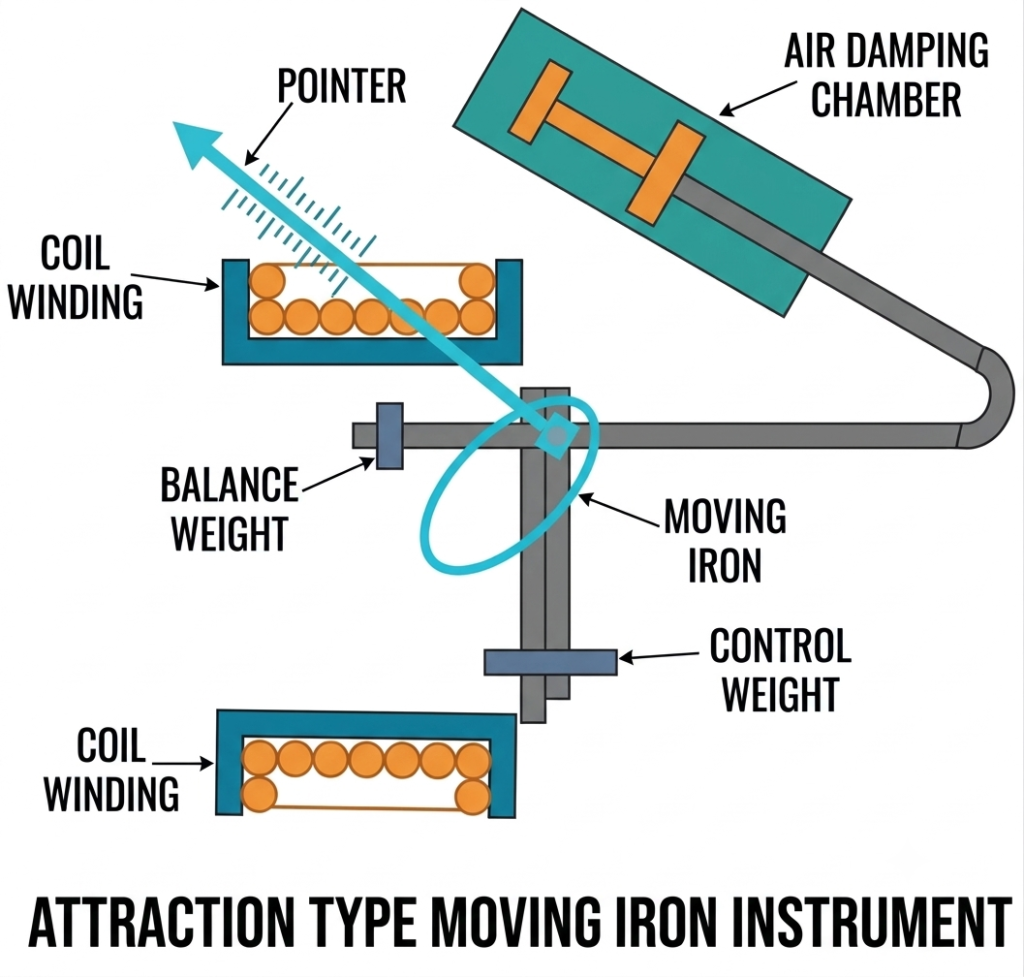
1. Attraction-Type Moving Iron Instrument
In an attraction-type moving iron instrument, a small piece of soft iron is mounted on a movable spindle near a current-carrying coil.
When current passes through the coil, a magnetic field is produced. The soft-iron piece becomes magnetized and is attracted toward the region of stronger magnetic field inside the coil.
This movement rotates the spindle and moves the pointer across the scale.
As the coil current increases, the magnetic field becomes stronger. Consequently, the attraction force and deflecting torque increase, producing greater pointer deflection.
The direction of attraction does not change when the current reverses. Therefore, the instrument can measure both AC and DC.
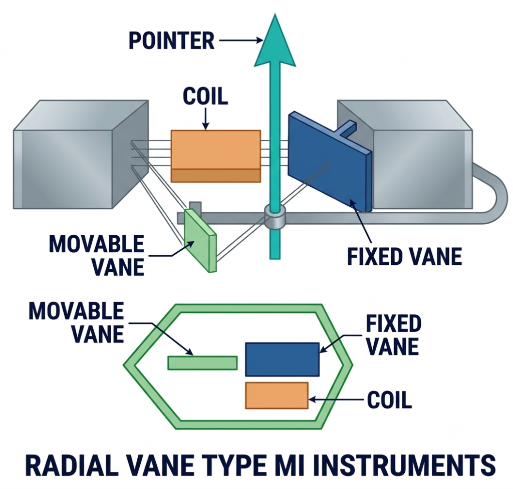
2. Repulsion-Type Moving Iron Instrument
A repulsion-type moving iron instrument consists of two soft-iron vanes placed inside a fixed current-carrying coil.
One vane is fixed, while the other is attached to a movable spindle connected to the pointer.
When current flows through the coil, both iron vanes become magnetized with the same polarity. Since like magnetic poles repel each other, the movable vane experiences a repulsive force and rotates the spindle.
The pointer moves according to the magnitude of the current.
When the current increases, the magnetic field becomes stronger, resulting in greater repulsion and increased pointer deflection.
In an AC circuit, the polarity of both iron vanes reverses simultaneously during every half-cycle. They continue to repel each other, so the deflecting torque remains in the same direction.
Theory of Attraction-Type Moving Iron Instrument
The attraction-type moving iron instrument operates because the movable iron element tends to move toward a position where the coil inductance is higher.
When current flows through the fixed coil, magnetic flux is produced. The magnetic field attracts the soft-iron element, causing it to move and rotate the pointer.
The deflecting torque can be derived using the energy stored in the magnetic field.
For a linear magnetic system, the stored magnetic energy is:
Where:
- = Magnetic energy stored in the system (joules)
- = Inductance of the coil (henry)
- = Current flowing through the coil (ampere)
The deflecting torque is obtained by taking the rate of change of magnetic energy with respect to the angular displacement at constant current.
Therefore,
Where:
- = Deflecting torque
- = Current flowing through the coil
- = Inductance of the coil
- = Angular deflection of the pointer
The equation shows that the deflecting torque depends on the square of the current and the rate of change of coil inductance with respect to angular displacement.
Controlling Torque
In a spring-controlled moving iron instrument, the controlling torque is proportional to the angular deflection.
It is expressed as:
Where:
- = Controlling torque
- = Spring constant
- = Angular deflection
At the final pointer position, the deflecting torque equals the controlling torque.
Therefore,
Substituting the torque equations:
Rearranging:
For a given instrument design, this relationship indicates that pointer deflection depends approximately on the square of the current when the change in inductance with angle is treated as constant over the operating range.
In an actual moving iron instrument, inductance varies with pointer position, and the magnetic properties of iron are not perfectly linear. Therefore, the scale is generally non-uniform and is calibrated experimentally.
Theory of Repulsion-Type Moving Iron Instrument
The working principle of a repulsion-type moving iron instrument is based on the repulsion between two similarly magnetized soft-iron elements.
When current flows through the fixed coil, both iron vanes become magnetized with the same polarity. The resulting repulsive force moves the movable vane away from the fixed vane.
The movable vane rotates the spindle and pointer, producing an indication on the scale.
The deflecting torque can also be expressed using the energy method:
Where (L) represents the effective inductance of the magnetic system at the particular pointer position.
For spring control:
At equilibrium:
Thus, the pointer deflection depends on the square of the current and the magnetic characteristics of the instrument.
The same torque principle applies to attraction-type and repulsion-type instruments, although their internal magnetic arrangements are different.
Why Can a Moving Iron Instrument Measure Both AC and DC?
A moving iron instrument can measure both AC and DC because its deflecting torque depends on the square of the current.
The torque equation is:
Since the current is squared, reversing its direction does not reverse the direction of the torque.
For an AC supply, the current changes direction during every half-cycle. However, the resulting magnetic action continues to produce torque in the same direction.
For a sinusoidal AC supply, the pointer responds to the average torque, which is proportional to the mean square current. Consequently, the instrument can be calibrated to indicate the RMS value of AC current or voltage.
Scale of Moving Iron Instrument
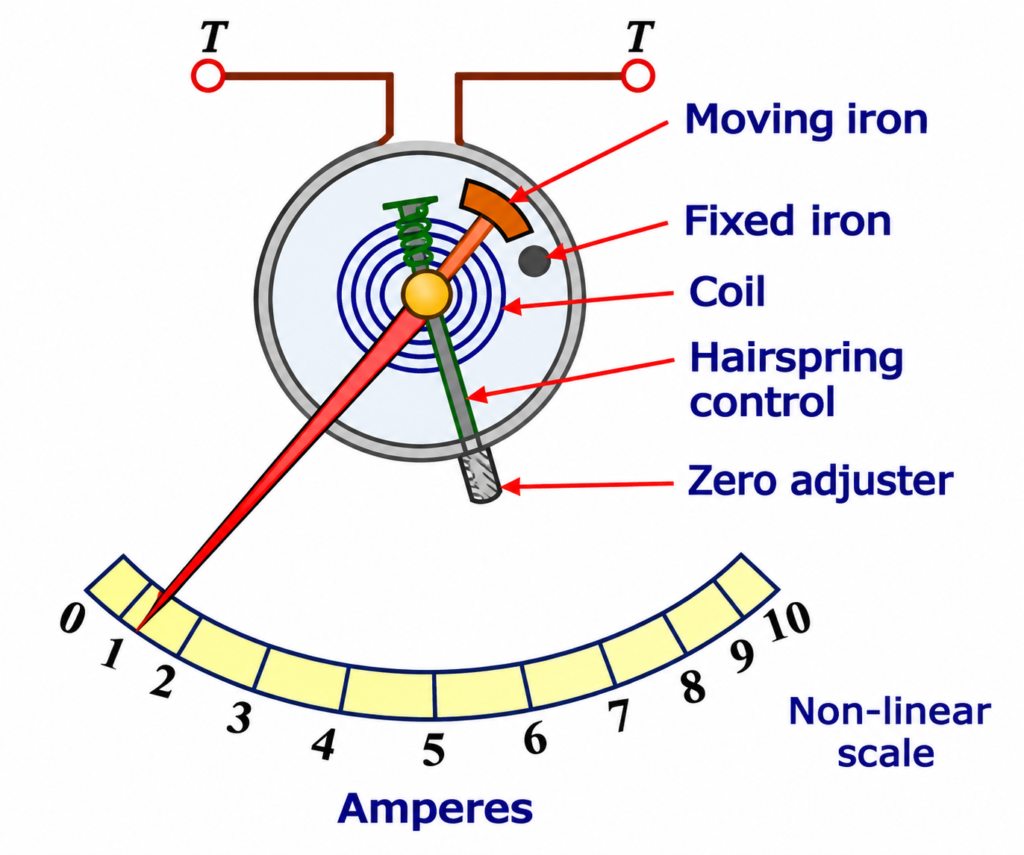
The scale of a moving iron instrument is generally non-uniform, especially near the lower end.
This happens because the deflecting torque is approximately proportional to the square of the current:
For spring control, the controlling torque is proportional to pointer deflection:
At equilibrium:
Therefore, the pointer movement is not directly proportional to current.
The scale markings are usually crowded near zero and become more widely spaced toward the upper end.
Advantages of Moving Iron Instruments
Moving iron instruments offer several advantages in electrical measurement:
- AC and DC measurement: They can measure both alternating and direct current.
- Simple construction: Their mechanical design is comparatively simple.
- Rugged design: They can withstand normal industrial operating conditions.
- Low manufacturing cost: They are generally economical compared with many other analog measuring instruments.
- High overload capacity: Their construction can be designed to withstand short-duration overloads.
- Wide applications: They are available in different current and voltage ranges for panel and laboratory use.
Disadvantages of Moving Iron Instruments
Despite their advantages, moving iron instruments have some limitations.
- Non-uniform scale: The scale is generally crowded near the lower end.
- Lower accuracy: Their accuracy is generally lower than that of precision PMMC instruments.
- Hysteresis error: Magnetic hysteresis in the iron parts can affect the measurement.
- Frequency error: Changes in frequency can affect the inductance and impedance of the coil.
- Stray magnetic field error: External magnetic fields can influence the instrument reading.
- Power consumption: The coil may consume more power than some other measuring instruments.
- Waveform influence: The response to AC depends on the waveform and frequency characteristics of the instrument.
Applications of Moving Iron Instruments
Moving iron instruments are commonly used in electrical measurement and industrial monitoring systems.
Their important applications include:
- AC ammeters: Measuring current in AC distribution circuits and electrical panels.
- AC voltmeters: Measuring voltage in industrial and commercial electrical systems.
- DC ammeters: Measuring direct current in DC circuits.
- DC voltmeters: Measuring DC supply voltage in electrical equipment.
- Switchboards: Monitoring current and voltage in power distribution panels.
- Industrial control panels: Providing local electrical measurements for machines and equipment.
- Power stations: Monitoring electrical parameters in auxiliary and distribution systems.
- Electrical laboratories: Performing general-purpose current and voltage measurements.
Difference Between Attraction-Type and Repulsion-Type Moving Iron Instruments
| Parameter | Attraction-Type | Repulsion-Type |
| Working principle | Attraction of soft iron toward a stronger magnetic field | Repulsion between similarly magnetized iron vanes |
| Iron elements | Generally one movable iron element | One fixed and one movable iron element |
| Movement | Iron element moves toward the coil’s stronger magnetic field | Movable vane moves away from the fixed vane |
| Construction | Comparatively simple | Relatively more complex |
| Deflecting torque | Produced by magnetic attraction | Produced by magnetic repulsion |
| Supply | AC and DC | AC and DC |
| Scale | Generally non-uniform | Generally non-uniform |
Conclusion
A moving iron instrument is a widely used electromechanical device for measuring current and voltage in AC and DC circuits. It operates through the magnetic attraction or repulsion of soft-iron elements placed inside a current-carrying coil.
The two main types are attraction-type and repulsion-type instruments. Both produce pointer movement through electromagnetic torque, and their deflecting torque is approximately proportional to the square of the current under the usual linear magnetic-system assumption.
Although moving iron instruments have limitations such as a non-uniform scale, hysteresis error, and frequency dependence, their simple construction, ruggedness, and ability to measure both AC and DC make them useful in industrial panels and general electrical measurement applications.
Read Next:
- Ammeter: Definition, Symbol, Working Principle, Types and Applications
- Clamp Meter Working Principle, Diagram & Uses
- Difference Between Indicating and Recording Instruments
- Null Type Instrument: Principle, Example, and Key Advantages
- Types of Measuring Instruments in Electrical Engineering
- Integrating Instruments: Classifications, Advantage and Applications
- Digital Instruments: Definition, Characteristics, Construction, Advantages, and Disadvantages
- Analog Instruments: Definition, Classification, and Working Principle
- Ammeter Shunt: Definition, Working Principle, Construction, Circuit Diagram, Formula and Applications
- Types of Voltmeter and Working Principle of Voltmeter