Substation earthing, also known as substation grounding, is one of the most important safety systems in an electrical power network. It provides a low-resistance path for fault currents, lightning currents, and static charges to safely dissipate into the ground. An effective earthing system protects personnel from electric shock, minimizes equipment damage, and ensures the reliable operation of protective relays and circuit breakers.
Every electrical substation, from an 11 kV distribution substation to a 765 kV extra-high-voltage (EHV) switchyard, requires a properly designed grounding system. Without adequate earthing, dangerous step and touch voltages can develop during electrical faults, creating serious safety hazards. The effectiveness of any grounding system depends on how the earthing system is installed.
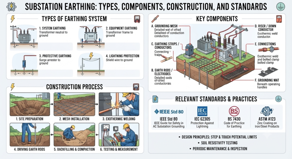
In this article, you’ll learn the objectives, importance, components, types, construction procedures, earth resistance requirements, and applicable standards for substation earthing.
What Is Substation Earthing?
Substation earthing is the process of connecting all non-current-carrying metallic parts of electrical equipment to the earth through a low-resistance grounding network. The primary objective is to maintain these metallic parts at or near earth potential during both normal and fault conditions.
The prime object of electrical earthing is to provide a zero-potential surface in and around the area where electrical equipment is installed. During an insulation failure or short circuit, the earthing system safely carries the fault current into the ground instead of allowing dangerous voltages to appear on equipment enclosures.
Electrical earthing is essential in:
- Power generating stations
- Transmission substations
- Distribution substations
- Industrial plants
- Commercial buildings
- Renewable energy installations
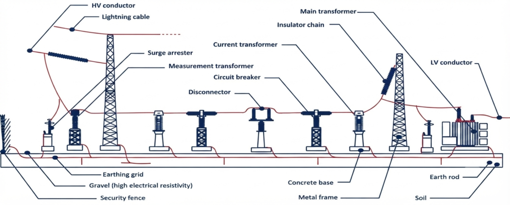
Objectives of Substation Earthing
The primary objectives of a substation earthing system are to establish a safe and reliable grounding network that protects the electrical installation during normal operation and fault conditions. An effective earthing system is designed to:
- Provide a low-resistance path for earth fault currents.
- Maintain exposed metallic parts at or near earth potential.
- Limit dangerous touch and step voltages.
- Ensure fast operation of protective relays and circuit breakers.
- Stabilize system voltage by providing a common earth reference.
- Dissipate lightning and switching surge currents safely.
- Comply with the requirements of IS 3043, IEEE Std 80, and other applicable standards.
Why Is Earthing Important in a Substation?
Electrical substations operate at high voltages and carry large fault currents. If a transformer, circuit breaker, or other equipment develops an insulation fault, its metal enclosure can become energized. Without an effective electrical earthing system, anyone touching the equipment may receive a dangerous electric shock, and the fault current may damage expensive equipment before protective devices operate.
A properly designed substation earthing system provides the following benefits:
- Protects personnel: Keeps exposed metallic parts at a safe potential, reducing the risk of electric shock.
- Protects electrical equipment: Safely diverts fault current to the ground, minimizing damage to transformers, switchgear, cables, and other substation equipment.
- Improves system reliability: Provides a dependable path for fault currents, enabling protective relays and circuit breakers to detect and clear faults quickly, thereby reducing outages.
- Provides lightning protection: Safely dissipates lightning and surge currents into the earth, protecting equipment from overvoltage damage.
- Supports control and communication systems: Maintains a stable ground reference for PLCs, SCADA systems, RTUs, communication equipment, and digital protection relays, reducing electrical noise and improving operational reliability.
Components of a Substation Earthing System
A substation earthing system consists of several interconnected components that work together to safely dissipate fault and lightning currents into the ground. Each component performs a specific function to ensure personnel safety, equipment protection, and reliable operation of the electrical system.
| Component | Function |
|---|---|
| Earth Mat (Ground Grid) | Forms the main grounding network by distributing fault current over a large area and minimizing step and touch voltages. |
| Earth Electrode | Provides a low-resistance electrical connection between the grounding system and the surrounding soil. |
| Earthing Conductor | Connects electrical equipment, structures, and earth electrodes to the earth grid, providing a continuous path for fault current. |
| Earthing Riser | Connects the underground earth mat to above-ground equipment such as transformers, circuit breakers, and support structures. |
| Earth Pit | Houses the earth electrode and provides an accessible location for earth resistance testing, inspection, and maintenance. |
| Equipment Bonding | Electrically bonds all exposed metallic parts together to maintain the same potential and eliminate dangerous voltage differences during faults. |
Types of Earthing Used in Substations
Different earthing methods are used in substations depending on the voltage level, soil conditions, fault current, and installation requirements. While mat earthing (ground grid earthing) is the preferred choice for modern substations, other methods such as plate, pipe, and strip earthing are also used for specific applications.
| Type of Earthing | Description | Typical Applications |
|---|---|---|
| Plate Earthing | Uses a copper or GI plate buried vertically in the ground to provide an earth connection. | Small substations, buildings, and industrial installations. |
| Pipe Earthing | Uses a perforated GI pipe installed vertically to achieve a low-resistance earth connection. | Distribution substations, transformers, and industrial plants. |
| Strip Earthing | Uses GI or copper strips buried horizontally in trenches to form an earthing conductor. | Cable trenches, transmission towers, and long structures. |
| Mat Earthing (Ground Grid) | Uses an interconnected network of GI flats or copper conductors buried below the switchyard. | EHV substations, switchyards, and power generating stations. |
1. Plate Earthing
Plate earthing uses a galvanized iron (GI) or copper plate buried vertically in the ground. It is suitable for locations where moderate fault currents are expected and is commonly used in small substations and industrial installations. Its main advantages include good current-carrying capability, a long service life, and suitability for medium-sized installations.
2. Pipe Earthing
Pipe earthing consists of a perforated galvanized iron (GI) pipe installed vertically in the ground. It is one of the most widely used earthing methods because it is economical, simple to install, and provides reliable performance in a wide range of soil conditions. It is preferred for its low installation cost, ease of installation, and minimal maintenance requirements.
3. Strip Earthing
Strip earthing uses GI or copper strips buried horizontally in trenches to provide a continuous grounding path. It is commonly used where long earthing conductors are required, such as cable trenches and transmission structures. Its key benefits include low earth resistance, effective performance in rocky or high-resistivity soil, and suitability for long grounding runs.
4. Mat Earthing (Ground Grid Earthing)
Mat earthing, also known as ground grid earthing, is the standard grounding method used in modern substations. It consists of an interconnected network of GI flats or copper conductors buried beneath the switchyard. The grid distributes fault current over a large area, reducing ground potential rise as well as step and touch voltages. It offers very low earth resistance, excellent fault current dissipation, uniform ground potential distribution, and enhanced protection against step and touch voltage hazards, making it the preferred choice for high-voltage and EHV substations.
Applications of Substation Earthing
Substation earthing is an essential part of every electrical installation where safe dissipation of fault and lightning currents is required. It protects personnel, electrical equipment, and the power system by maintaining a low-resistance path to the ground. Depending on the voltage level and application, earthing systems are widely used in the following installations:
- Power generating stations to safely dissipate fault currents from generators and auxiliary equipment.
- Transmission and distribution substations to protect transformers, switchgear, busbars, and other high-voltage equipment.
- GIS (Gas-Insulated Switchgear) substations to provide reliable grounding for compact, high-voltage installations.
- Industrial substations supplying power to manufacturing plants, refineries, steel mills, and other process industries.
- Renewable energy plants, including solar and wind power stations, to protect inverters, transformers, and associated electrical equipment.
- Railway traction substations to ensure safe operation of traction transformers and overhead electrification systems.on
Substation Earthing Construction
The construction of a substation earthing system involves installing a network of grounding conductors and electrodes that provide a low-resistance path for fault and lightning currents. The earthing installation process includes earth mat installation, earthing risers, equipment bonding, and earth pit construction. The installation should be carried out according to the approved design drawings and applicable standards, such as IS 3043, to ensure long-term safety and reliability.
The main construction activities include:
- Laying the Earth Mat: Install the main ground grid using 75 × 10 mm GI flats buried at the specified depth and welded at all intersections to maintain electrical continuity.
- Installing Earthing Risers: Connect the underground earth mat to transformers, switchgear, steel structures, and other equipment using 50 × 6 mm GI flats.
- Connecting Equipment to Earth Pits: Securely connect electrical equipment to designated earth pits through earthing conductors to provide an effective fault current path.
- Constructing Pipe Earthing: Install GI pipe electrodes with suitable earth-enhancing material, such as bentonite, where required, in accordance with IS 3043.
Earth Mat Installation
The earth mat (ground grid) forms the foundation of a substation earthing system. It consists of interconnected 75 × 10 mm galvanized iron (GI) flats buried beneath the switchyard to provide a low-resistance path for fault and lightning currents. The earth mat is installed according to the approved layout, with all intersections securely welded to ensure continuous electrical conductivity.
The installation process typically involves:
- Excavating trenches to the specified depth (generally around 600 mm).
- Laying 75 × 10 mm GI flats as per the approved earth grid layout.
- Welding all intersections and joints to maintain electrical continuity.
- Applying bituminous paint to welded joints for corrosion protection.
- Backfilling and compacting the trenches after inspection and continuity testing.
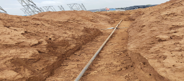
Typical earth mat installation in substation is shown in the diagram below.
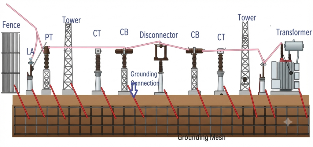
Earthing Riser Installation
Earthing risers connect the underground earth mat (ground grid) to above-ground electrical equipment, providing a continuous path for fault currents to flow safely into the grounding system. They are typically installed using 50 × 6 mm galvanized iron (GI) flats and securely connected to equipment earthing terminals.
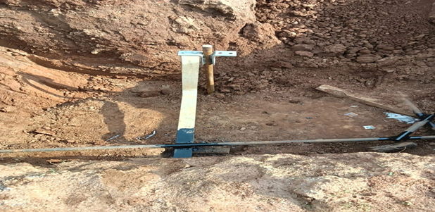
The installation process includes:
- Connecting the earth mat to equipment earthing terminals using 50 × 6 mm GI flats.
- Ensuring proper alignment, adequate mechanical support, and secure connections.
- Welding joints to maintain continuous electrical conductivity.
- Applying bituminous paint and wrapping welded joints with insulating tape to protect against corrosion.
Common Installation Mistakes
Improper installation can significantly reduce the effectiveness of a substation earthing system and compromise both safety and equipment protection. The following mistakes should be avoided during construction and maintenance:
- Poor welding of GI flats: Incomplete or defective welds increase joint resistance and reduce electrical continuity.
- Loose earthing connections: Loose or improperly tightened connections can interrupt the fault current path.
- Inadequate burial depth: Shallow installation exposes the earthing conductors to mechanical damage and environmental effects.
- Improper backfilling: Poor compaction or the presence of stones and debris around conductors can increase earth resistance.
- Corroded joints and conductors: Lack of corrosion protection can weaken the earthing system over time.
- Missing equipment bonding: Failure to bond all metallic structures may create dangerous touch voltages during faults.
- High-resistance earth pits: Poor soil conditions, damaged electrodes, or inadequate maintenance can result in excessive earth resistance.
Proper installation, periodic inspection, and regular earth resistance testing help ensure that the substation earthing system remains safe, reliable, and compliant with applicable standards.
Recommended Earth Resistance Values
The effectiveness of a substation earthing system depends on maintaining a low earth resistance, which allows fault and lightning currents to dissipate safely into the ground. Although the required value varies with the type of electrical installation, the earth resistance should be as low as reasonably practicable and comply with the applicable standards and project specifications.
Typical Earth Resistance Limits
| Installation | Maximum Earth Resistance |
|---|---|
| Power Generating Station | 0.5 Ω |
| EHV Substation | 1.0 Ω |
| 33 kV Substation | 2.0 Ω |
| Distribution Transformer Structure | 5.0 Ω |
| Transmission Tower Footing | 10.0 Ω |
Substation Grounding Standards
The design, installation, testing, and maintenance of a substation earthing system should comply with recognized national and international standards. These standards provide guidelines for grounding system design, conductor sizing, safety limits, testing procedures, and protection against electric shock.
| Standard | Purpose |
|---|---|
| IS 3043 | Code of Practice for Earthing. |
| IEEE Std 80 | Safety in AC Substation Grounding. |
| IEEE Std 142 | Industrial and Commercial Grounding. |
| CBIP Publication 302 | Guidelines for Earthing of AC Power Systems. |
| Indian Electricity Rules | Specifies electrical safety and earthing requirements. |
Testing and Maintenance
Regular testing and maintenance are essential to ensure that the substation earthing system continues to provide a low-resistance path for fault currents throughout its service life. Periodic inspections help identify corrosion, loose connections, damaged conductors, and other issues that may affect system safety and performance.
Routine maintenance activities include:
- Measuring earth resistance at regular intervals.
- Checking the electrical continuity of the earthing network.
- Inspecting welded joints and conductors for corrosion or damage.
- Tightening loose bolted connections.
- Cleaning and inspecting earth pit chambers.
- Replacing damaged or corroded earthing conductors and components.
Conclusion
Substation earthing is an essential part of every electrical substation, providing a safe, low-resistance path for fault and lightning currents. A properly designed and installed earthing system protects personnel from electric shock, safeguards transformers, switchgear, and other electrical equipment, and ensures the reliable operation of protective devices during fault conditions.
Among the various earthing methods, earth mat (ground grid) earthing is the preferred choice for modern substations because it offers low earth resistance, effective fault current dissipation, and better control of step and touch voltages. By following recognized standards such as IS 3043 and IEEE Std 80, and carrying out regular inspection, testing, and maintenance, utilities and industries can improve the safety, reliability, and long-term performance of their substation grounding systems.
Read Next: