Equivalent resistance is a fundamental concept in electrical engineering that simplifies the analysis of resistor networks. Instead of calculating the behavior of multiple resistors individually, a complex circuit can be replaced with a single equivalent resistance that draws the same current and produces the same electrical response as the original network. This approach makes circuit calculations faster, reduces complexity, and helps engineers analyze both simple and complex electrical systems with greater accuracy.
Understanding equivalent resistance is essential for applying Ohm’s Law and Kirchhoff’s Laws to determine current, voltage, and power in electrical circuits. It is one of the first concepts learned in circuit theory because it forms the foundation for solving practical engineering problems and designing reliable electrical systems.
The concept of equivalent resistance is widely used in electrical engineering, electronics, power systems, control systems, substation engineering, household wiring, and industrial electrical installations. Whether designing an electronic circuit, troubleshooting electrical equipment, or analyzing a power distribution network, calculating equivalent resistance is a critical skill for engineers, technicians, and students.
What Is Equivalent Resistance?
Equivalent resistance is the total resistance offered by a group of resistors connected in a circuit. It represents the value of a single resistor that can replace an entire resistor network between two terminals without changing the circuit’s electrical behavior. When the same supply voltage is applied, the equivalent resistor draws the same current and dissipates the same amount of power as the original combination of resistors.
Whether the resistors are connected in series, parallel, or a combination of both, calculating the equivalent resistance simplifies circuit analysis. Instead of solving a complex network with multiple resistors, engineers replace it with a single resistor of equivalent value, making it much easier to determine current, voltage drops, and power using Ohm’s Law and Kirchhoff’s Laws.
To understand equivalent resistance, it is helpful to first understand electrical resistance. Resistance is the property of a material or electrical component that opposes the flow of electric current. It is measured in ohms (Ω). A higher resistance restricts current flow, while a lower resistance allows more current to pass through the circuit. By combining individual resistances into one equivalent resistance, complex electrical networks become much simpler to analyze, design, and troubleshoot.
Equivalent Resistance in a Parallel Circuit
In a parallel circuit, all resistors are connected across the same two nodes, creating multiple paths for the flow of electric current. Because each resistor is connected directly across the power supply, the voltage across every parallel branch remains the same. However, the current divides among the branches according to the resistance of each branch.
A branch with lower resistance carries more current, while a branch with higher resistance carries less current. The total current supplied by the source is equal to the sum of the currents flowing through all parallel branches.
The equivalent resistance of a parallel circuit is the value of a single resistor that can replace all the parallel resistors without changing the circuit’s overall electrical behavior. When the parallel resistor network is replaced by its equivalent resistance, the source delivers the same total current as before, provided the supply voltage remains unchanged.
Equivalent Resistance Formula for Parallel Circuit
The equivalent resistance of resistors connected in parallel is calculated using the following formula:
where:
- (Rp) = Equivalent resistance of the parallel circuit
- (R1, R2, R3, Rn) = Individual resistor values connected in parallel
Unlike a series circuit, adding more resistors in parallel reduces the total resistance of the circuit. Each additional branch provides another path for current to flow, making it easier for electric current to travel from the source to the load. As a result, the equivalent resistance of a parallel circuit is always smaller than the resistance of the smallest individual resistor.
Example of Equivalent Resistance in a Parallel Circuit
Consider two resistors, 6 Ω and 6 Ω, connected in parallel across a DC power supply. Since both resistors have the same value, the current divides equally between the two branches.
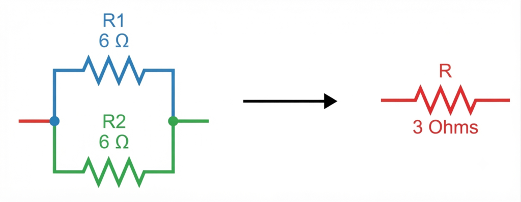
Using the parallel resistance formula:
Therefore,
Although each branch contains a 6 Ω resistor, the combined effect of the two parallel paths is equivalent to a single 3 Ω resistor. The reduction in equivalent resistance occurs because the current has two equal paths instead of one. If additional parallel branches are added, the equivalent resistance decreases further, allowing the circuit to draw more current from the source.
This principle is widely used in household wiring, industrial power distribution, lighting circuits, substations, and electronic systems, where multiple electrical devices must receive the same supply voltage while operating independently.
Equivalent Resistance in a Series Circuit
A series circuit is formed when electrical components are connected one after another in a single continuous path. Since there is only one path available, the same current flows through every resistor in the circuit. As the electric current passes through each resistor sequentially, every component carries an identical current regardless of its resistance value.
The equivalent resistance of a series circuit is the resistance of a single resistor that can replace all the individual resistors while producing the same current for a given supply voltage. Replacing a series resistor network with its equivalent resistance makes circuit analysis much simpler without affecting the overall electrical behavior of the circuit.
Equivalent Resistance Formula for Series Circuit
The equivalent resistance of resistors connected in series is calculated using the following formula:
where:
- (Req) = Equivalent resistance of the series circuit
- (R1, R2, R3, Rn) = Individual resistor values connected in series
Unlike a parallel circuit, adding more resistors in series increases the total circuit resistance. As the equivalent resistance increases, the current drawn from the power source decreases according to Ohm’s Law.
Example of Equivalent Resistance in a Series Circuit
Suppose two resistors of 8 Ω and 5 Ω are connected in series.
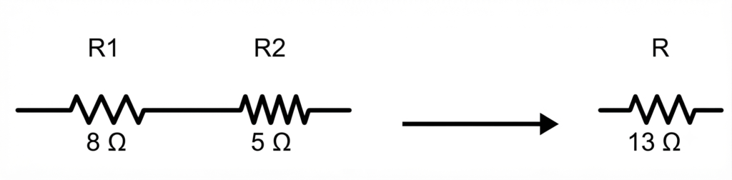
The equivalent resistance is obtained by simply adding their resistance values:
Therefore, the two resistors behave exactly like a single 13 Ω resistor connected across the same voltage source. The same current flows through both resistors, while the supply voltage is divided between them according to their resistance values.
Series connections are widely used in voltage divider circuits, fuse protection circuits, current-limiting applications, battery packs, and electronic control circuits, where maintaining the same current through all connected components is essential.
Solved Example Problems on Equivalent Resistance
Eaxample 1: Find equivalent resistance across A and B in the below given circuit diaagram.
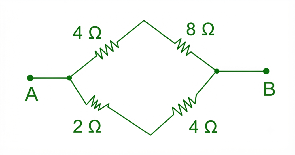
Solution-
Upper branch :(In Series)
Lower branch: 🙁 In Series)
Now,
Using parallel formula,
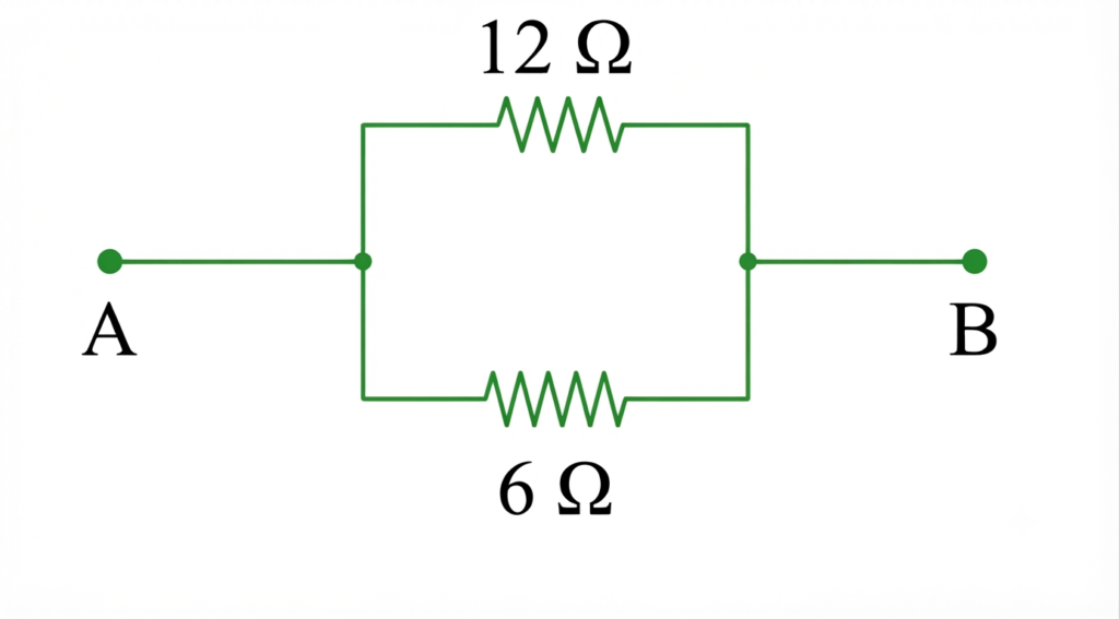
Therefore,
R = 4 Ω
Example 2: Calculate the Equivalent Resistance of the Following Resistor Network Between Points A and B.
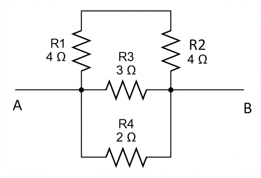
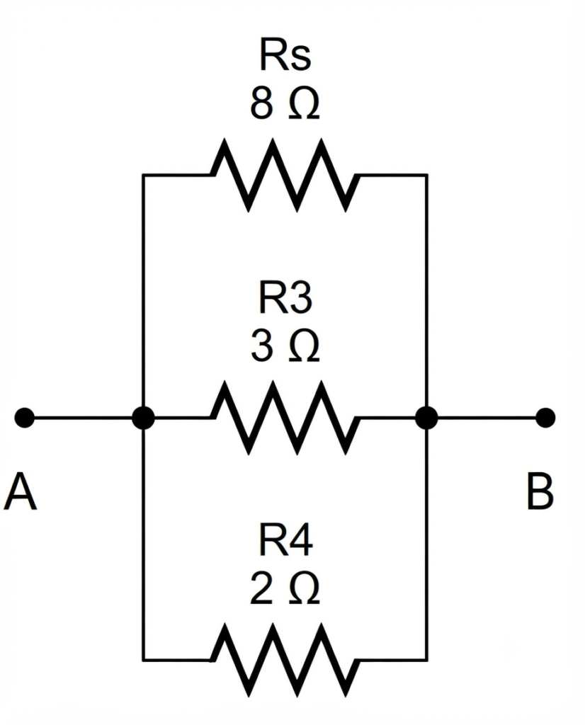
The 4 Ω resistors R1 and R are connected in series. Therefore, their equivalent resistance is obtained by adding their individual resistance values:
Resistors Rs, R3, and R4 are connected in parallel. The equivalent resistance of this parallel network is calculated as:
Example 3: Determine the equivalent resistance between terminals A and B for the resistor network shown below.
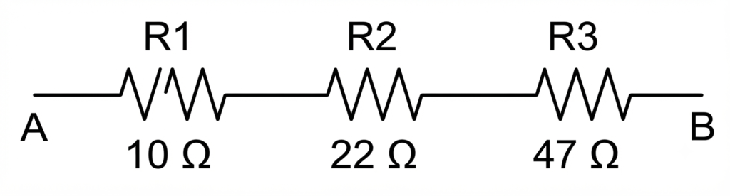
The equivalent resistance of resistors connected in series is calculated by adding the resistance of each individual resistor, as shown below.
Complex Equivalent Resistance Problems
Example 1: Calculate the equivalent resistance of the given resistor network.
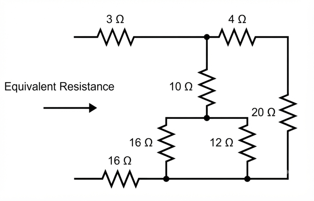
To calculate the equivalent resistance, the resistors connected in series and parallel are combined step by step. In this circuit, the 16 Ω and 12 Ω resistors are connected in parallel. Therefore, their equivalent resistance is calculated as follows:
Also, the 4 Ω and 20 Ω resistors are connected in series. For resistors in series, the equivalent resistance is obtained by adding their resistance values. Therefore, the equivalent resistance is given as:
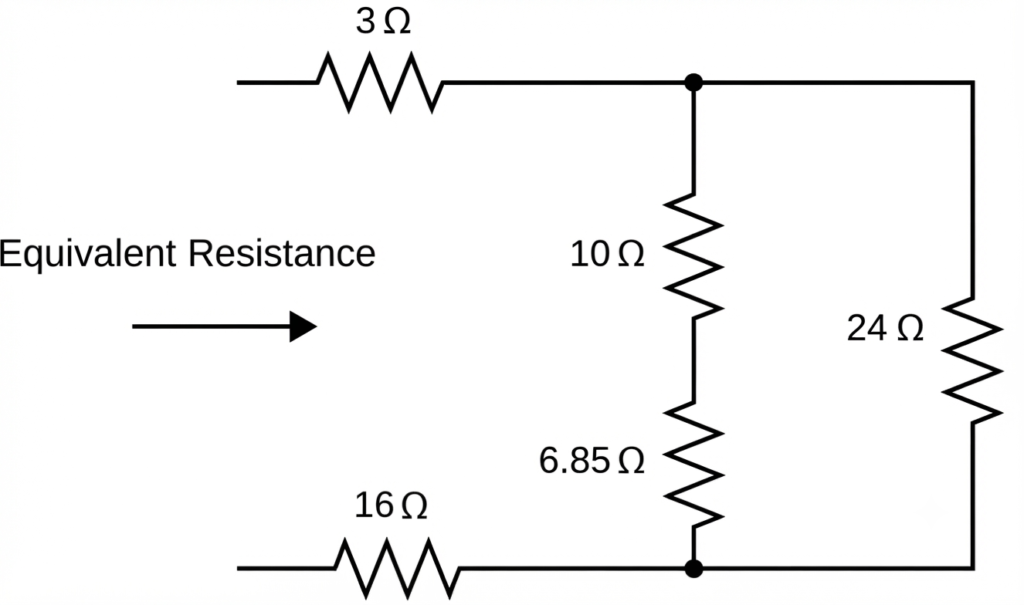
After the reduction, we observe that the 10 Ω and 6.85 Ω resistors are connected in series. For resistors connected in series, their resistance values are added together. Therefore, the equivalent resistance is given as:
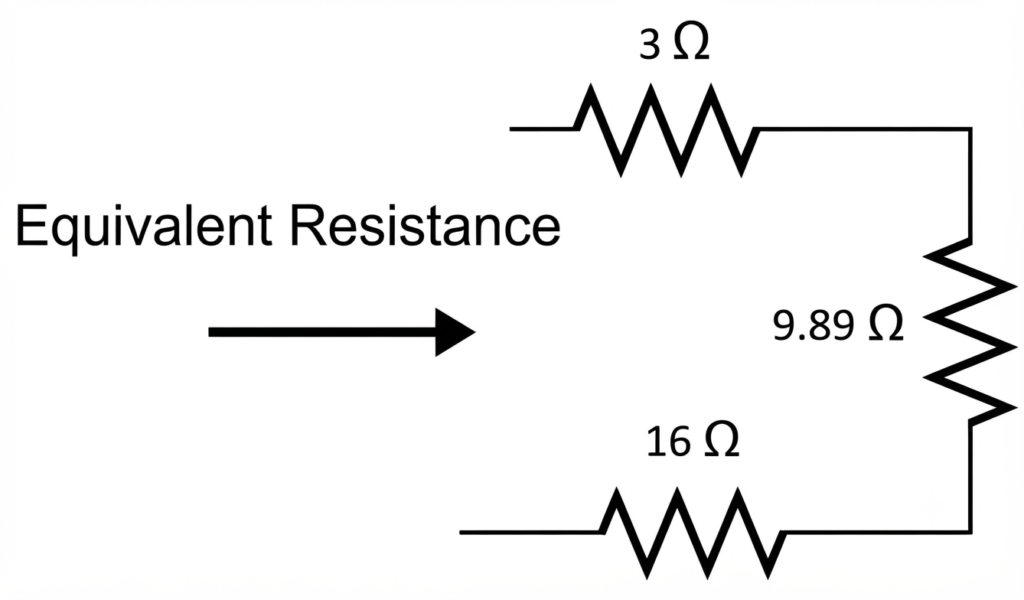
This 16.85 Ω resistor is connected in parallel with the 24 Ω resistor. For parallel-connected resistors, the reciprocal of the equivalent resistance is equal to the sum of the reciprocals of the individual resistances. Therefore, their equivalent resistance is given as:
Example 2: Find the equivalent resistance between points A and B.
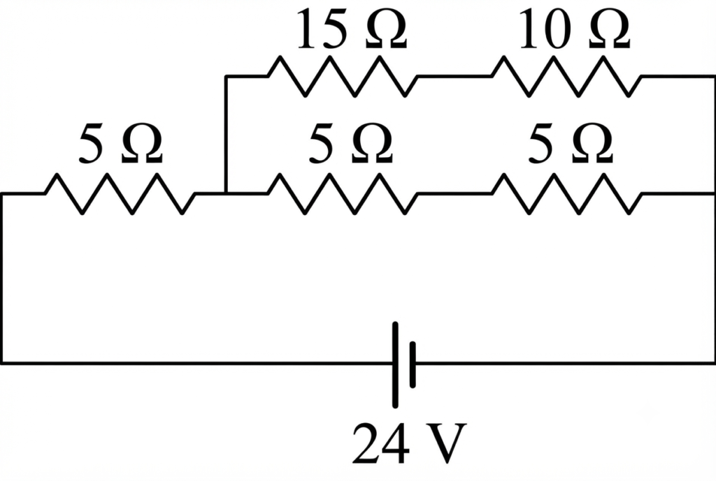
The 5 Ω and 5 Ω resistors are connected in series. Therefore, the equivalent resistance is given as:
The 15 Ω and 10 Ω resistors are connected in series. Therefore, the equivalent resistance is given as:
The 10 Ω and 25 Ω resistors are connected in parallel. Therefore, the equivalent resistance is given as:
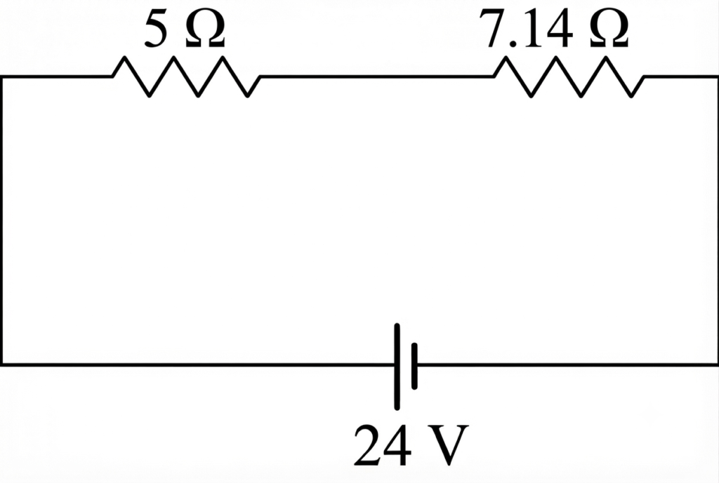
The 5 Ω and 7.14 Ω resistors are connected in series. Therefore, the equivalent resistance is given as:
The current in the circuit is:
Conclusion
Understanding equivalent resistance is essential for anyone working with electrical or electronic circuits. By replacing a network of resistors with a single equivalent resistor, circuit analysis becomes faster, simpler, and more accurate.
Knowing the equivalent resistance formula for both series and parallel circuits allows you to calculate the total circuit resistance with confidence. In a series connection, resistances add directly because the same current flows through every resistor, whereas in a parallel connection, the reciprocal method is used because each branch has the same voltage while the current is divided.
Whether you are learning how to calculate equivalent resistance, solving circuit problems, designing electrical systems, or troubleshooting faults, mastering this concept provides a strong foundation for understanding more advanced topics in electrical engineering.
Frequently Asked Questions (FAQs)
Equivalent resistance is the resistance of a single resistor that can replace multiple resistors in a circuit without changing the overall current and voltage behavior.
Each resistor adds additional opposition to the same current path, so the total resistance is the sum of all individual resistances and is therefore greater than any one resistor alone.
Parallel branches provide multiple paths for current to flow, reducing the total opposition. As a result, the equivalent resistance is always less than the smallest individual resistor.
Household wiring uses parallel connections so that every appliance receives the full supply voltage and can operate independently. A fault in one appliance does not interrupt power to the others.
Read Next: