The characteristics of a DC shunt generator describe how its voltage and current change under different operating conditions. These characteristics are represented by curves obtained from practical tests and are used to evaluate the generator’s performance, voltage regulation, efficiency, and load-handling capability.
Since the field winding of a DC shunt generator is connected in parallel with the armature, the field current depends on the terminal voltage. As the load changes, the terminal voltage also changes, which affects the field current and the generated EMF. This makes the performance of a DC shunt generator different from that of a separately excited generator.
The characteristics of a DC shunt generator help engineers:
- Study the variation of terminal voltage with load.
- Determine the generated EMF under different operating conditions.
- Evaluate voltage regulation.
- Understand the effects of armature reaction and armature resistance.
- Determine the operating limits of the generator.
Types of Characteristics of DC Shunt Generator
The performance of a DC shunt generator is studied using the following three characteristics:
- Open Circuit Characteristic (O.C.C.) – Shows the relationship between the generated EMF and the field current when the generator runs at constant speed without any external load. It is also known as the no-load saturation characteristic and is used to study voltage build-up and determine the critical field resistance.
- Internal Characteristic – Shows the relationship between the generated EMF (E) and the armature current (Ia). This characteristic includes the effect of armature reaction but does not include the voltage drop across the armature resistance.
- External Characteristic – Shows the relationship between the terminal voltage (V) and the load current (IL). Since it includes both the armature resistance drop and the effect of armature reaction, it represents the actual performance of the generator under load.
Among these three characteristics, the external characteristic is the most important because it indicates how the terminal voltage varies with load current during normal operation.
External Characteristic of DC Shunt Generator
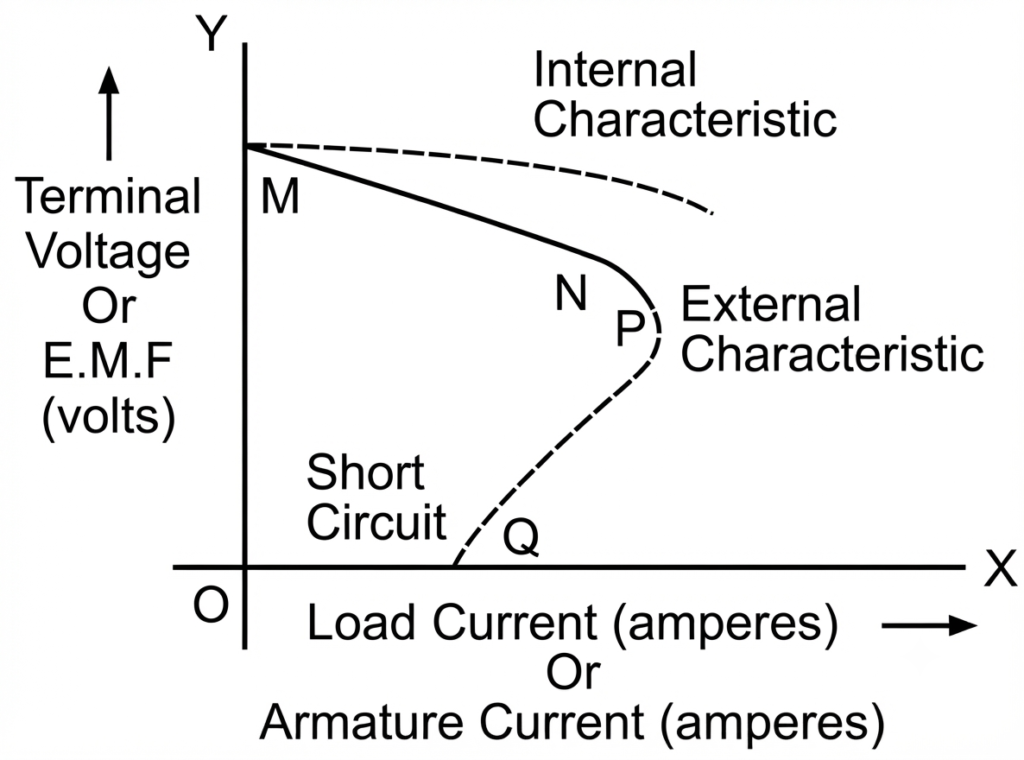
The external characteristic of a DC shunt generator is the graph between the terminal voltage (V) and the load current (IL) while the generator operates at a constant speed. This characteristic shows how the terminal voltage changes as the electrical load connected to the generator increases.
Load Test to Obtain the External Characteristic
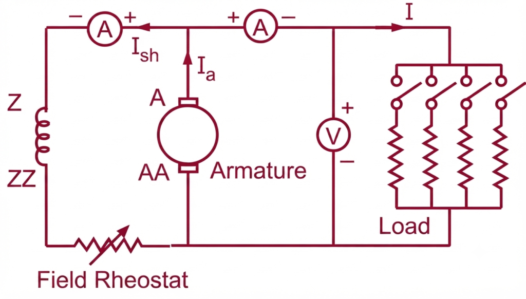
The external characteristic is obtained by performing a load test, which is carried out in a manner similar to that of a separately excited DC generator.
The test is performed as follows:
- Drive the generator at its rated speed using a suitable prime mover.
- Adjust the field rheostat until the generator produces its rated no-load terminal voltage.
- Keep the position of the field rheostat fixed throughout the test.
- Gradually connect the load by decreasing the load resistance.
- Record the corresponding values of load current and terminal voltage at each load condition.
- Plot the terminal voltage on the Y-axis against the load current on the X-axis.
The resulting curve represents the external characteristic of the DC shunt generator.
The external characteristic of a shunt generator is illustrated in the image below.
Why Does the Terminal Voltage Drop with Increasing Load?
As the load on the generator increases, the terminal voltage gradually decreases. This reduction occurs due to several factors acting simultaneously.
- Armature resistance drop: As the armature current increases, the voltage drop across the armature resistance ( Ia Ra) also increases, reducing the terminal voltage.
- Armature reaction: The magnetic field produced by the armature weakens the main field flux, resulting in a lower generated EMF.
- Reduction in shunt field current: Since the field winding is connected across the generator terminals, any decrease in terminal voltage also reduces the field current. The weaker field current further decreases the generated EMF, causing an additional drop in terminal voltage.
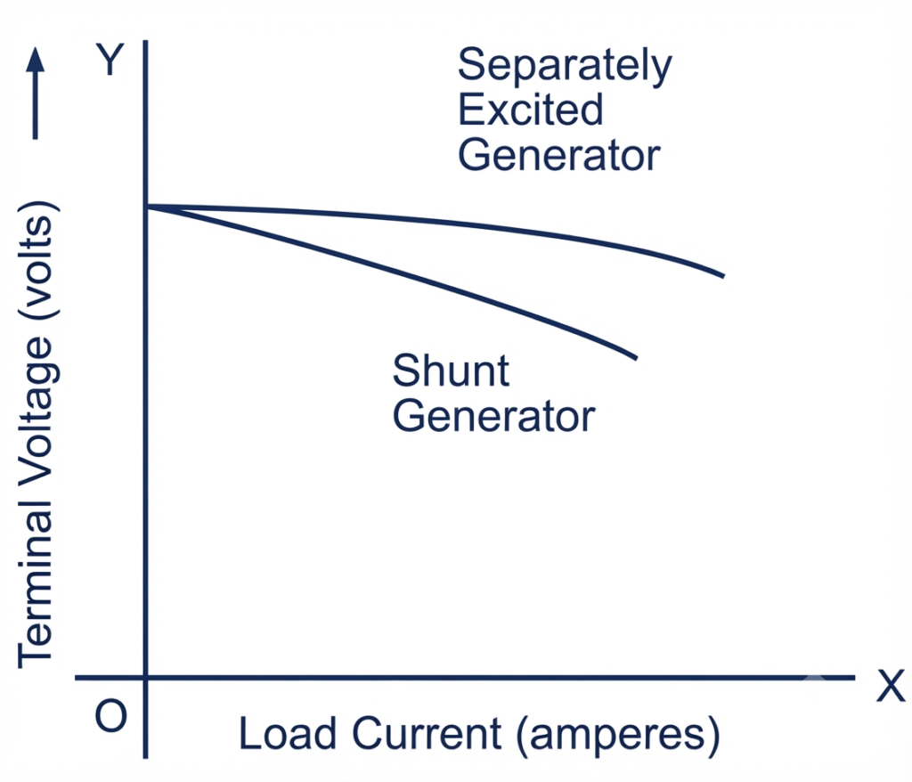
Because of this cumulative effect, the terminal voltage of a DC shunt generator falls more rapidly than that of a separately excited generator, whose field current remains practically constant. Therefore, the external characteristic of a DC shunt generator is more drooping than that of a separately excited generator.
Explanation of the External Characteristic Curve
The external characteristic of a DC shunt generator can be divided into three distinct regions( Fig-1).
Region MN – Normal Operating Region
The portion MN represents the normal operating range of the generator.
As the external load resistance is gradually reduced, the load current increases. During this region, the terminal voltage decreases slowly due to the combined effects of:
- armature resistance drop,
- armature reaction, and
- reduction in shunt field current.
The voltage reduction is gradual, allowing the generator to operate satisfactorily under normal loading conditions.
Region NP – Rapid Voltage Drop Region
Beyond point N, the terminal voltage begins to decrease much more rapidly.
At higher loads, armature reaction becomes stronger, the armature resistance drop increases further, and the lower terminal voltage reduces the shunt field current significantly. These effects reinforce one another, causing the generated EMF to decrease rapidly.
Although the load resistance continues to decrease, the generated voltage falls faster than the current can increase. As a result, the external characteristic becomes much steeper.
Region PQ – Short-Circuit Region
Beyond point P, the terminal voltage continues to fall until the generator approaches the short-circuit condition.
When the external load resistance becomes almost zero, the generator terminals are practically short-circuited. Consequently, the terminal voltage falls nearly to zero, and because the shunt field winding is connected across the terminals, the field current also becomes almost zero.
Under this condition, the generator produces only a small short-circuit current, which is due to the weak residual magnetism remaining in the poles. This residual magnetic flux is further weakened by armature reaction.
An interesting feature of a DC shunt generator is that its short-circuit current is considerably lower than its rated full-load current because the loss of field excitation limits the current automatically.
The characteristic therefore bends backward after point P, clearly indicating that the load current begins to decrease even though the load resistance continues to reduce.
Critical Load Resistance
For a DC shunt generator to build up its terminal voltage while connected to a load, the external load resistance must not fall below a certain minimum value. This minimum resistance is known as the critical load resistance.
If the load resistance is less than the critical load resistance during voltage build-up, the generator fails to excite and cannot develop its rated terminal voltage.
Therefore, a DC shunt generator has two critical resistances:
- Critical field resistance, which determines whether voltage build-up occurs in the field circuit.
- Critical load resistance, which determines whether the generator can build up voltage while supplying a load.
These two critical resistances play an important role in the successful operation of a DC shunt generator.
Internal Characteristic of DC Shunt Generator
The internal characteristic of a DC shunt generator shows the relationship between the generated EMF (E) and the armature current (Ia). Unlike the external characteristic, it represents the voltage generated inside the armature before the voltage drop across the armature resistance is taken into account.
This characteristic helps in understanding the effect of armature reaction on the generated EMF and is useful for analyzing the generator’s internal performance.
Equation of the Internal Characteristic
In a DC shunt generator, the armature current is the sum of the load current and the shunt field current. Therefore,
The generated EMF is given by
where:
- E = Generated EMF (V)
- V = Terminal voltage (V)
- Ia = Armature current (A)
- IL = Load current (A)
- Ish = Shunt field current (A)
- Ra = Armature resistance (Ω)
How to Obtain the Internal Characteristic
The internal characteristic is obtained from the same load test used to determine the external characteristic.
For each load condition:
- Measure the terminal voltage and load current.
- Calculate the shunt field current using the terminal voltage and field resistance.
- Determine the armature current using:
- Calculate the generated EMF using:
- Plot the generated EMF against the corresponding armature current.
The resulting graph is known as the internal characteristic of the DC shunt generator.
(Insert Internal Characteristic Diagram Here)
Effect of Shunt Field Current
In most practical DC shunt generators, the shunt field current is very small compared to the load current. Therefore, for approximate calculations,
This simplification introduces very little error and is commonly used in engineering calculations.
Why Is the Internal Characteristic Above the External Characteristic?
The internal characteristic always lies above the external characteristic because it represents the generated EMF before subtracting the armature resistance voltage drop.
The difference between the two characteristics is equal to the armature voltage drop:
As the load increases, the armature current increases, resulting in a larger voltage drop across the armature resistance. Consequently, the gap between the internal and external characteristics becomes more noticeable at higher loads.
Graphical Determination of Internal Characteristic
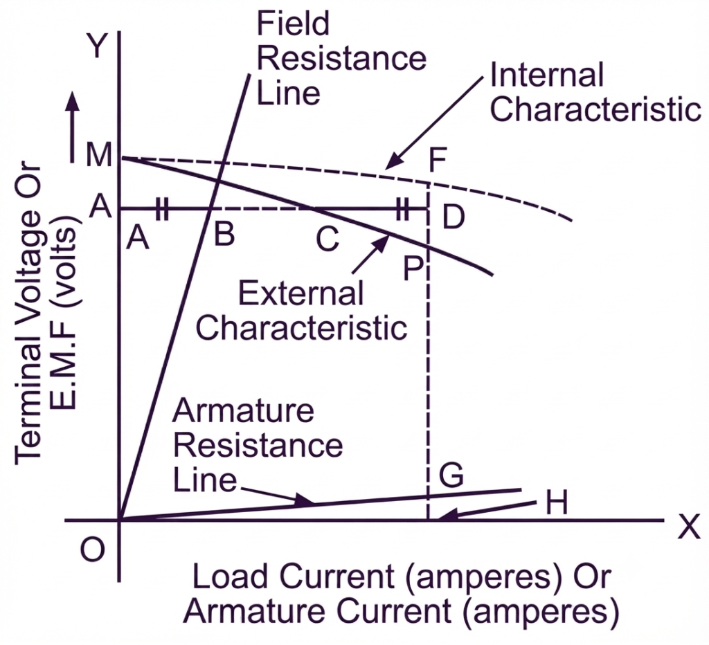
The internal characteristic can also be obtained graphically from the external characteristic without directly calculating the generated EMF for every load point.
This method is widely used because it provides an accurate internal characteristic using the load test data and a few graphical constructions.
Procedure for Graphical Determination
- Draw the external characteristic using the readings obtained from the load test.
- Draw the field resistance line () on the same graph.
- Draw the armature resistance line (IRa).
- Select any point C on the external characteristic.
- Draw a horizontal line through point C.
- From the field resistance line, determine the corresponding shunt field current.
- Add the shunt field current to the load current to obtain the armature current.
- Using the armature resistance line, determine the corresponding armature voltage drop:
- Add this voltage drop to the terminal voltage.
- Mark the corresponding point on the graph.
- Repeat the same procedure for several points and join them with a smooth curve.
The resulting curve represents the internal characteristic of the DC shunt generator.
Advantages of the Graphical Method
The graphical method offers several advantages:
- It eliminates the need for repeated numerical calculations.
- It provides a visual understanding of the relationship between the external and internal characteristics.
- It accurately accounts for the shunt field current and armature resistance drop.
- It is widely used in electrical machine laboratories and engineering education.
Comparison of Characteristics of DC Shunt Generator
The following table provides a quick comparison of the three DC generator characteristics, highlighting the variables plotted and the information each characteristic reveals about generator performance.
| Characteristic | Variables Plotted | Purpose |
|---|---|---|
| Open Circuit Characteristic (O.C.C.) | Generated EMF vs Field Current | Shows voltage build-up and magnetic saturation under no-load conditions. |
| Internal Characteristic | Generated EMF vs Armature Current | Shows the effect of armature reaction while neglecting the armature resistance voltage drop. |
| External Characteristic | Terminal Voltage vs Load Current | Represents the actual operating performance of the generator under load. |
Key Takeaways
- The external characteristic shows how the terminal voltage changes with load current.
- The internal characteristic represents the relationship between generated EMF and armature current.
- Compared with the DC series generator characteristics, the external characteristic is more drooping than that of a separately excited generator because the field current decreases with terminal voltage.
- The external characteristic bends backward near the short-circuit region due to the combined effects of armature reaction, armature resistance drop, and reduced field current.
- The short-circuit current of a DC shunt generator is much lower than its rated full-load current because the field excitation almost disappears under short-circuit conditions.
- The internal characteristic can be obtained either by calculations using load test data or by the graphical method.
- A DC shunt generator has two critical resistances: the critical field resistance and the critical load resistance, both of which are essential for successful voltage build-up.
Read Next: