Discover the essential Parts of the Transformer and their functions in this detailed guide. Learn how each component—like the core, windings, conservator, breather, and more—contributes to efficient transformer operation and safety. Perfect for students, engineers, and professionals.
What is a Transformer?
A transformer is a static electrical device that efficiently transfers electrical energy between circuits using electromagnetic induction. It changes the voltage level of alternating current (AC) without affecting its frequency. Since it has no moving parts, the transformer operates with high efficiency, typically more than 95%, and is widely used in power systems.
When alternating current flows through the primary winding, it creates a varying magnetic field. This field induces a voltage in the secondary winding, and the voltage level is determined by the turn’s ratio between the windings. This working principle ensures safe, efficient voltage transformation for electricity transmission and distribution across long distances.
The concept of electromagnetic induction was discovered by Michael Faraday, leading to the invention of transformers in the late 1800s. Since then, they’ve become vital for power systems, enabling voltage conversion, reducing transmission losses, balancing loads, ensuring safety, and regulating voltage for homes, businesses, and industrial operations worldwide.
Key components of a transformer include the core, which carries magnetic flux, and the primary and secondary windings, which handle input and output voltages. These three form the basic working structure of a transformer, allowing the device to operate seamlessly and efficiently in a variety of electrical applications.
Beyond its core components, a transformer includes several supporting parts such as cooling systems, Buchholz relay, HT and LT bushings, breather, conservator tank, oil tank, explosion vent, and tap changer. These elements enhance its safety, cooling, fault protection, and voltage regulation capabilities, ensuring reliable operation under diverse electrical conditions.
14 Basic Parts of Transformer
The different transformer parts are as follows:
1). Core
2). Winding
3). Insulation
4). Tank
5). Terminals and Bushings
6). Transformer Oil
7). Conservator Tank (or) Oil Conservator
8). Breather
9). Radiators and Fans
10). Explosion Vent
11). Tap Changers
12). Buchholz Relay
13). Temperature Gauge
14). Cooling Tubes
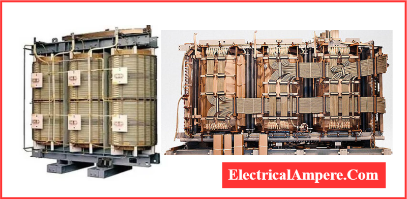
1). Core
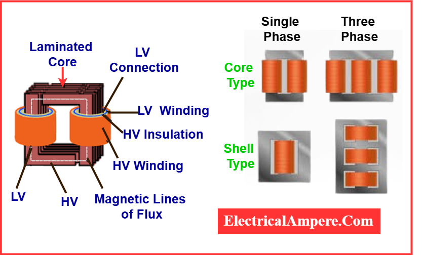
The core is a crucial part of a transformer, serving as the magnetic path for flux linking the primary and secondary windings. Made from soft iron or grain-oriented silicon steel, it ensures low reluctance, reducing hysteresis and eddy current losses for efficient energy transfer with minimal interference and heat generation.

The core is built by stacking thin, insulated laminations of steel, limiting eddy current formation. The carbon content is kept below 0.1%, and silicon is added to enhance electrical properties. This construction enhances magnetic performance and reduces losses, ensuring optimal operation in both power and distribution transformers across electrical networks.
Each phase’s primary and secondary windings are placed on the transformer limbs, which are magnetically connected by the yokes. These structural elements form a closed magnetic loop, promoting efficient flux flow. The design ensures magnetic continuity and balances flux between limbs, contributing to the overall performance and reliability of the transformer.
Transformer cores are categorized into two types: core type and shell type. In the core type, windings surround the core limbs. In contrast, the shell type encloses the windings within the core, offering better compactness and magnetic shielding. Both designs aim to optimize energy transfer and reduce core-related losses.
2). Winding
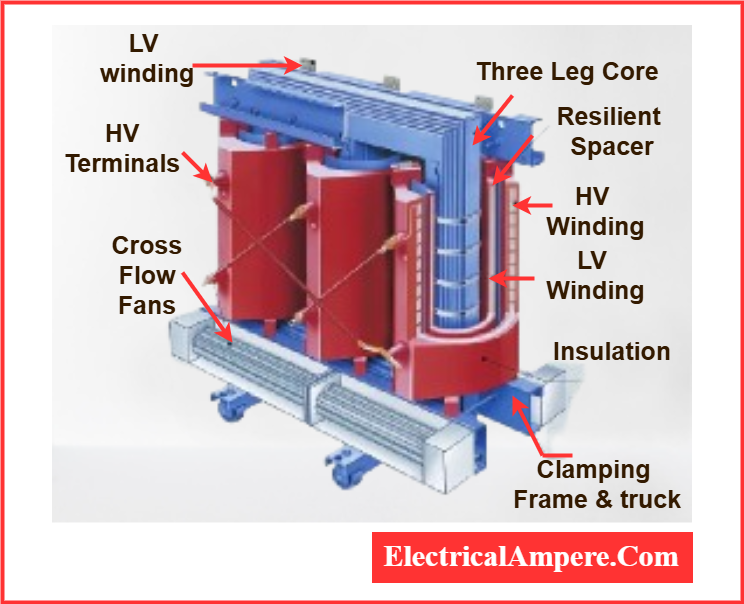
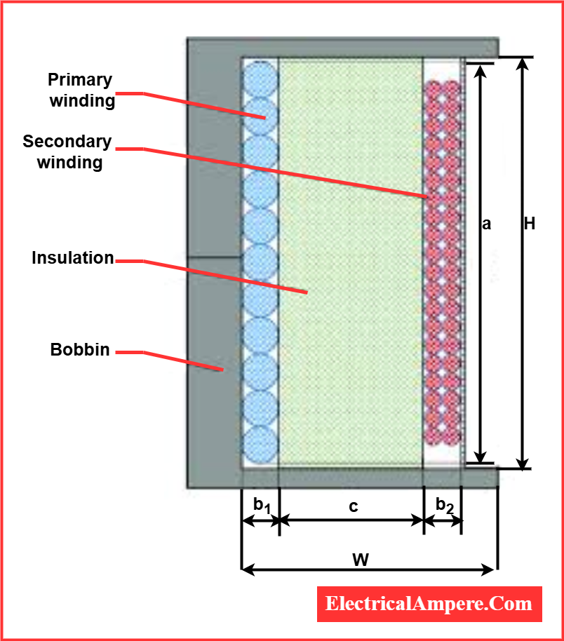
The primary and secondary windings in a transformer are crucial for transferring electrical energy between high and low voltage circuits. Made from copper or aluminium, they are insulated from the core and each other. The winding type depends on factors like current rating, short-circuit power, temperature rise, impedance, and surge voltage.
The primary winding, or HV (High Voltage) winding, is connected to the input voltage, while the secondary, or LV (Low Voltage) winding, connects to the load. In shell-type transformers, the LV coils are positioned at the center, and HV coils are placed between them. In core-type transformers, four winding configurations are used.
These configurations include multi-layer windings, helical windings, disc windings, and foil windings, chosen based on the number of turns and current-carrying capacity. The primary winding induces a magnetic field, and the secondary winding generates voltage based on the turns ratio. This enables the transformer to step up or step down voltage for effective electricity distribution.
Read detiled aricle on: LV and HV Winding in Transformer – Why LV Placed Near the Core?
3). Insulation
Insulation is the most crucial component of transformers, as failures in insulation can lead to severe damage. Transformer insulation refers to the use of specific materials or methods to prevent or reduce the transfer of heat, electricity, or sound between parts. It is required:
- Between the core and windings,
- Between each turn of the winding, and
- Between any current-carrying component and the tank.
Insulation is essential for the safe and efficient operation of the equipment, providing electrical, thermal, and mechanical protection. It ensures electrical safety, maintains temperature stability, and enhances mechanical durability. High dielectric strength, excellent mechanical properties, and resistance to high temperatures are key features of effective insulation.
Transformer insulation is made from a range of materials, including synthetic materials, paper, cotton, and other specialized substances, which contribute to the equipment’s longevity and reliability.
4). Tank
The main tank of a transformer is a sealed enclosure that houses essential components, including the core, windings, insulation, cooling systems, and auxiliary devices. It serves two primary functions:
- It shields the windings and core from the external environment, ensuring their mechanical stability.
- It provides support for additional components and acts as a container for the oil.
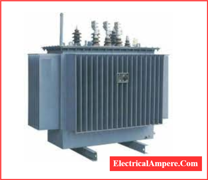
The tank body is formed by rolling steel plates into vessels, which are equipped with cooling tubes and lifting hooks. In some cases, aluminium sheets are used instead of steel plates to reduce weight and minimize stray losses, though aluminium tanks are more expensive than steel ones. The tank protects the transformer from external damage or contamination, maintaining the integrity of the internal components.
5). Terminals and Bushings
Transformer terminals are essential connection points that facilitate the safe and efficient transfer of electrical energy to and from the transformer.
The primary terminals receive high-voltage electrical energy, while the secondary terminals deliver lower voltage to loads. These terminals are installed on bushings, attached to the ends of the windings, and provide a safe path for electrical connections.
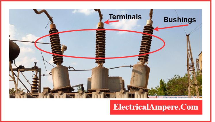
Bushings, which act as insulators, create a barrier between the terminals and the tank. The transformer’s tank is positioned above the bushings, allowing the wires connecting the terminals to the windings to pass through safely.
Transformer terminals ensure the seamless flow of electricity by enabling the connection of power lines, secondary circuits, and other components, making them vital for efficient energy distribution. Bushings are typically made from porcelain or epoxy resins.
6). Transformer Oil
Transformer oil plays a crucial role in oil-immersed transformers by enhancing heat dissipation, aiding in fault detection, and providing additional insulation between the conducting elements. It is primarily made from hydrocarbon mineral oil, which consists of olefins, paraffin, aromatics, and naphthenes.
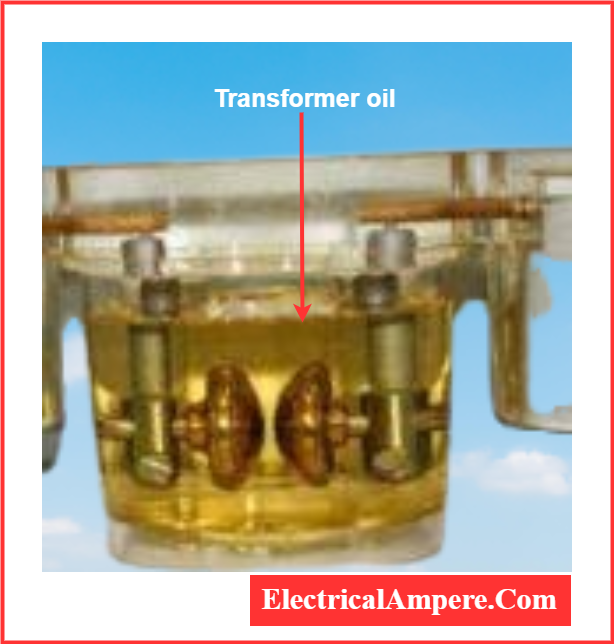
Transformer oil has specific characteristics, including a density of 0.96 kg/cm³, a flashpoint of 310°C, and a relative permeability of 2.7. These properties make it an essential component for the efficient operation and safety of transformers, helping to maintain temperature stability, prevent electrical breakdowns, and ensure reliable performance. The oil also assists in reducing the risk of transformer fires and enhances the longevity of the transformer.
7). Conservator Tank (or) Oil Conservator
The conservator is an expansion tank connected to the transformer’s oil tank, designed to accommodate oil volume changes due to temperature fluctuations. Positioned above the tank and bushings, it helps manage the expansion and contraction of the transformer oil as temperatures rise and fall. Some oil conservators are equipped with a rubber bladder to maintain pressure stability.
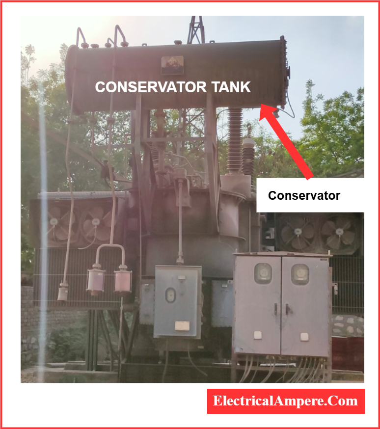
Function: The primary role of the oil conservator is to ensure a stable oil level within the transformer. It achieves this by providing enough space to accommodate oil volume changes, effectively compensating for oil expansion and contraction. Connected to the main tank via a pipe, the conservator ensures the oil level remains within the desired operating range. A level indicator is installed to display the current oil level inside the conservator.
8). Breather
A breather, also known as a silica gel breather or air breather, is an essential component in oil-immersed transformers with a conservator tank. It controls the quality of air entering and leaving the transformer shell, ensuring that the transformer oil remains dry and free from moisture and contaminants.
The primary function of the breather is to prevent moisture and dust from entering the transformer. As temperature changes cause the transformer oil to expand and contract, air enters and exits the conservator tank.
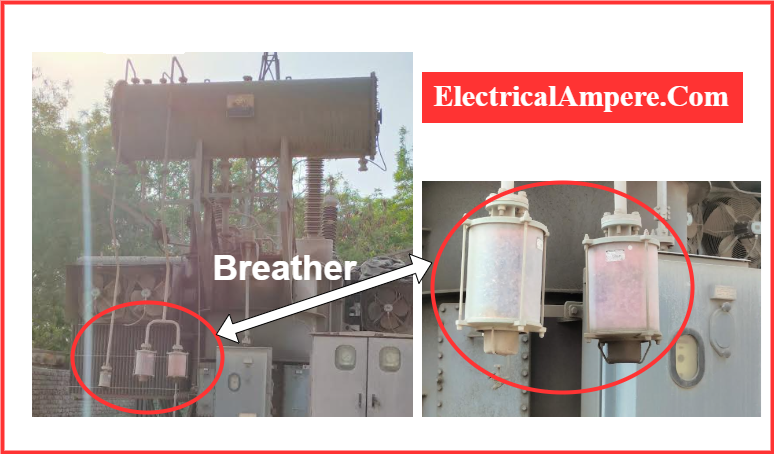
The breather prevents this air from carrying moisture, which could damage the transformer’s insulation properties. By using silica gel, the breather absorbs moisture, ensuring only dry air enters the conservator, thus preserving the integrity and stability of the transformer oil and maintaining the insulation properties for optimal performance.
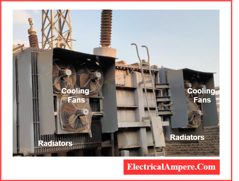
9). Radiators and Fans
Heat is generated due to power losses in the transformer. While most dry transformers rely on natural air cooling, oil-immersed transformers use a variety of cooling techniques to manage heat.
Radiators and cooling fans are installed on the transformer tank based on factors like the kVA rating, power losses, and required cooling capacity.
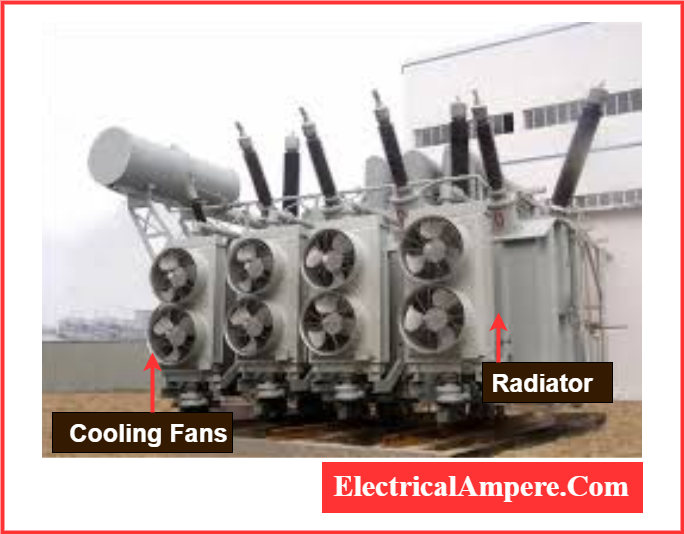
The transformer oil absorbs heat from the core and windings, which is then released through the radiator. In larger transformers, forced cooling is achieved by radiator-mounted cooling fans, which enhance heat dissipation and maintain optimal operating temperatures.
10). Explosion Vent
An explosion vent in a transformer functions as an emergency outlet for air and oil fumes. It consists of a metallic pipe that extends near the conservator tank, equipped with a diaphragm at one end. In the event of an oil leak, pressure inside the tank can build to dangerous levels.
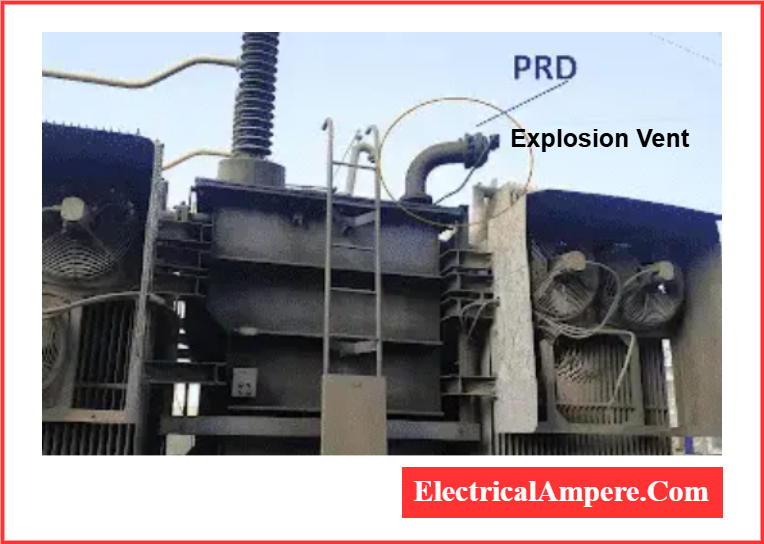
The explosion vent typically opens at a pressure of around 0.3 to 0.5 bar (approximately 4.35 to 7.25 psi). When this pressure is reached, the diaphragm ruptures at a relatively low pressure, allowing internal forces to escape safely into the environment. This prevents catastrophic damage and ensures the transformer’s safety.
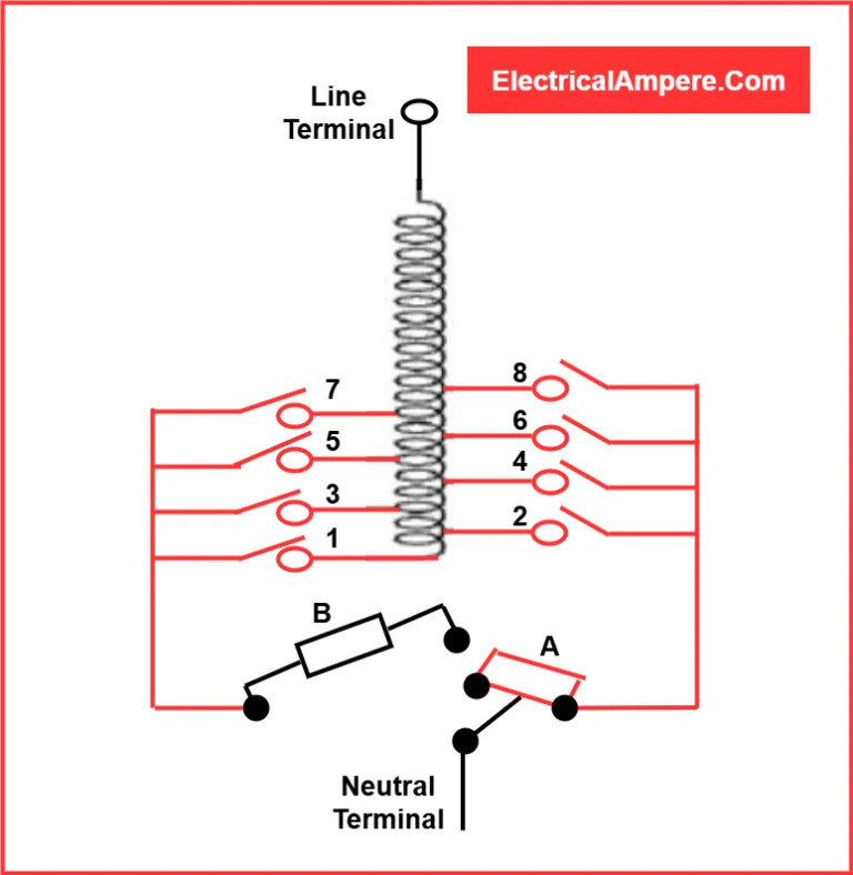
11). Tap Changers
Tap changers are devices used in transformers to adjust the secondary voltage by changing the transformer’s turn ratio as needed. They are essential for maintaining the desired output voltage under varying load conditions. Tap changers help regulate voltage fluctuations, ensuring stable operation and preventing damage to electrical equipment.
There are two main types of tap changers:
- On-Load Tap Changers: These can operate while the transformer is under load, allowing voltage adjustments without interrupting the power supply. This feature is crucial in applications requiring continuous power, such as industrial processes and grid distribution.
- Off-Load Tap Changers: These can only function when the transformer is not supplying any load, requiring a shutdown to make adjustments. This type is typically used in less demanding applications or for transformers that do not experience frequent load changes.
Additionally, automatic tap changers are available, which can adjust the tap position without manual intervention, enhancing operational efficiency and reducing human error. These automatic systems are commonly used in modern grid systems, where voltage regulation needs to be more precise and dynamic.
12). Buchholz Relay
The Buchholz relay is an essential safety device for oil-immersed transformers rated above 500 kVA. It detects faults within the transformer that are submerged in oil by sensing the presence of gases and oil movement. This relay is typically mounted on the pipe connecting the conservator tank to the main tank.
When a fault such as a short circuit occurs, the transformer oil decomposes, generating gases like methane, carbon monoxide, and hydrogen. These gases migrate through the connecting conduit toward the conservator tank. The Buchholz relay detects the presence of these gases and activates the trip and alarm circuits.
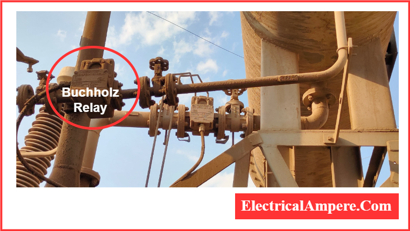
Once the gases are detected, the Buchholz relay triggers the trip circuit, interrupting the current flow to the primary winding and opening the circuit breaker. This action protects the transformer by preventing further damage and alerting operators to take corrective measures. The relay plays a critical role in maintaining transformer safety, especially in large transformers that are prone to more significant faults.
13). Temperature Gauge
A temperature gauge is a critical device used to monitor the temperature of a power transformer. Positioned on top of the transformer tank, it provides real-time temperature readings to ensure the transformer operates within safe thermal limits.
The Winding Temperature Indicator (WTI) measures the temperature of the winding, while the Oil Temperature Indicator (OTI) tracks the temperature of the transformer oil.
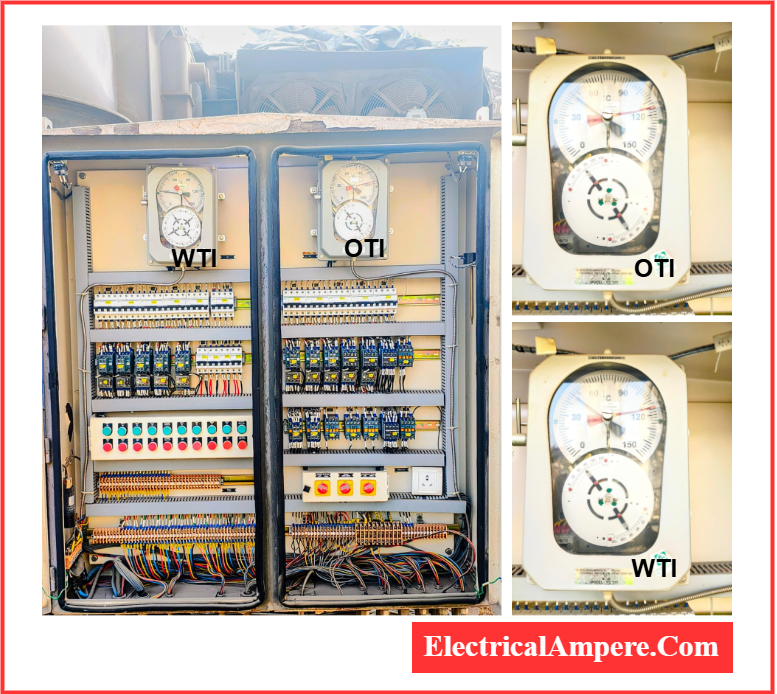
If either temperature exceeds the predefined threshold, the gauge triggers a light or alarm to notify operators of potential overheating. This helps prevent damage to the transformer by allowing timely intervention to cool down the system, ensuring longevity and reliable performance.
14). Cooling Tubes
As the name suggests, cooling tubes are designed to cool transformer oil. Inside the transformer, oil may circulate freely or be mechanically circulated.
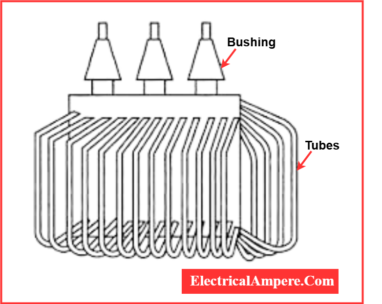
During natural circulation, the heated oil rises to the top as its temperature increases. In forced circulation systems, a pump is used to move the oil between the hot and cold zones, ensuring efficient heat dissipation. This circulation process maintains the transformer’s operating temperature within safe limits, preventing overheating and enhancing the overall performance and lifespan of the transformer.
14). Drain Valve
Usually positioned at the bottom of the transformer tank, the drain valve is used for replacing the transformer oil. By opening this valve, much like a faucet, the oil can be easily drained and replaced, ensuring proper maintenance and operation of the transformer.
In the case of a fire, the drain valve is crucial for quickly removing oil from the tank, reducing the risk of the oil fueling the fire and helping to control the situation more effectively.
Summary- Components of the Transformer
Here is a table listing the parts of a transformer and their applications:
| Part | Application |
|---|---|
| Core | Provides a low reluctance path for the magnetic flux, enhancing transformer efficiency. |
| Windings (Primary & Secondary) | Facilitate energy transfer between the primary and secondary circuits; copper or aluminum used for efficient current conduction. |
| Insulation | Electrically isolates the windings and core to prevent short circuits and electrical arcing. |
| Oil Tank | Contains transformer oil for insulation and cooling, ensuring safe operation and preventing overheating. |
| Oil Conservator | Accommodates oil expansion and contraction due to temperature fluctuations, maintaining stable oil levels. |
| Cooling Tubes | Circulate oil for cooling, ensuring proper heat dissipation and maintaining the transformer’s temperature. |
| Breather | Prevents moisture from entering the transformer by filtering air going in and out of the conservator, preserving oil quality. |
| Tap Changer | Allows for voltage adjustment in the transformer by altering the turn ratio of the windings. |
| Buchholz Relay | Detects faults in oil-immersed transformers by sensing gas accumulation or oil flow abnormalities. |
| Explosion Vent | Provides an emergency outlet for air and oil fumes, preventing pressure buildup from oil leaks and maintaining safety. |
| Temperature Gauge | Monitors the temperature of the transformer to ensure it remains within safe operating limits. |
| Drain Valve | Used for draining and replacing transformer oil, ensuring proper maintenance and aiding in fire control by quickly removing oil. |
| Terminal | Connects the transformer to incoming and outgoing wires, allowing the transfer of electrical energy. |
| Bushings | Insulate and provide a pathway for electrical current to pass from the windings to external wiring while preventing leakage. |
| Cooling Fans | Mounted on larger transformers, these fans force the circulation of oil, enhancing the cooling process. |
| Radiators | Used to dissipate heat from the transformer oil, ensuring that the temperature remains within safe limits. |
| Winding Taps | Provide multiple voltage adjustment points for the transformer, enabling fine-tuning of the output voltage. |
| Silica Gel Breather | Removes moisture from air entering the transformer, ensuring dry and clean air, protecting the oil and insulation from contaminants. |
| Pressure Relief Valve | Protects the transformer from overpressure by venting excess pressure to prevent damage to the tank. |
This table highlights the various parts of a transformer and their crucial applications for safe and efficient operation.
Why are Copper Windings Used in Transformers?
Copper windings are commonly used in transformers and other electrical machines due to the distinct properties of copper, which make it highly suitable for efficient electrical energy transfer. Here are the key reasons why copper is preferred:
- High Electrical Conductivity: Copper has excellent conductivity, which allows it to efficiently conduct electrical current. This characteristic significantly reduces power losses in the transformer windings, ensuring better performance and energy efficiency.
- Reduced Power Losses: Due to its superior conductivity, copper helps minimize the losses that typically occur during the transmission of electricity. This reduction in power losses translates to higher efficiency in transformer operation, which is essential for maintaining performance and longevity.
- Increased Ductility: Copper is highly ductile, meaning it can be easily bent or shaped without breaking. This property is particularly important in transformer windings, where the conductor must be wound tightly around the transformer core. The flexibility of copper allows for compact winding designs, reducing the volume and weight of the conductor used.
- Compact and Lightweight Design: The increased ductility of copper enables tighter wrapping of windings around the core, which reduces the overall amount of copper needed while maintaining the desired electrical characteristics. This results in a more compact and lighter transformer, which is crucial for space and weight optimization in various applications.
- Durability and Corrosion Resistance: Copper is also known for its durability and resistance to corrosion, which ensures a longer lifespan for the transformer windings. This makes copper an ideal material for use in harsh environmental conditions where long-term reliability is essential.
In summary, copper’s excellent conductivity, ductility, and durability make it the ideal material for transformer windings, helping to optimize performance, reduce power losses, and ensure efficient and reliable operation.
Comparison of Components: Single-Phase vs. Three-Phase Transformers
Single-phase and three-phase transformers share many similar components, but they also exhibit differences in design and construction due to their distinct operating principles. Here’s a detailed comparison of their components:
Common Components:
- Core: Both transformer types use a laminated iron or steel core to provide a low reluctance path for magnetic flux, which improves transformer efficiency.
- Primary and Secondary Windings: Both types have primary and secondary windings made of insulated copper or aluminium wire for energy transfer between input and output circuits.
- Insulation: Insulation materials are used in both to electrically isolate the windings and the core, ensuring safe operation and preventing electrical arcing.
- Cooling System: Transformers generate heat, so both require cooling systems mounted on the transformer tank to dissipate heat and maintain safe operating temperatures.
- Conservator: Both single-phase and three-phase transformers can have conservator tanks. These are expansion tanks that are connected to oil-filled transformers to accommodate oil volume changes.
- Oil Tank: Both transformers use oil tanks to act as a cooling and insulation medium, which enhances the overall transformer performance and safety.
Differences in Components:
- Windings Arrangement: Single-phase transformers typically have two windings (primary and secondary), while three-phase transformers have three primary and three secondary windings. This difference reflects the distinct requirements of single-phase and three-phase systems.
- Core Design: Three-phase transformers often feature a more complex core design, with three-legged or five-legged cores, depending on the configuration, to accommodate the multiple windings and phases.
- Size and Weight: Three-phase transformers are generally larger and heavier than single-phase transformers due to their higher power capacity and the more extensive core and winding structures.
- Winding Taps: Single-phase transformers may have multiple winding taps to adjust the voltage. In contrast, three-phase transformers may have additional taps to accommodate the varying voltage requirements of different loads and phases in a three-phase system.
These differences ensure that each type of transformer is optimized for its specific application, with three-phase transformers typically being used for larger, industrial-scale applications due to their ability to handle higher power loads efficiently.
Read Next: