The Q factor or Quality Factor measures how efficiently a circuit component like an inductor or capacitor stores energy compared to how much it loses as heat. It directly impacts bandwidth, damping, and resonance behavior. A higher Q indicates lower energy loss and sharper selectivity—ideal for applications like filters and oscillators.
What is Q Factor? (Definition)
The Quality Factor (Q) is defined as the ratio of energy stored to energy dissipated per cycle. It indicates how closely a real inductor behaves like an ideal one in AC circuits. The Q Factor is a dimensionless number that describe damping in a circuit and its bandwidth relative to the center frequency.
We know that a coil is known for storing energy when some current passes through it. In an ideal inductor or coil, energy is stored without any loss. However, real inductors always have some internal resistance, which causes power loss in the form of heat.
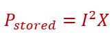
Energy stored in a coil is.
The energy lost in a coil’s resistance is.

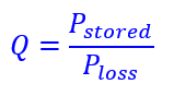
The Quality factor is;
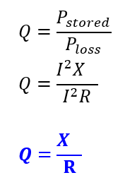
We can calculate the Quality Factor of a coil by knowing its reactance and resistance.
A higher reactance means more energy storage, resulting in a better Q.
Lower coil resistance leads to reduced power loss and therefore a higher Q.
Q Factor Formulas in Electrical Circuits
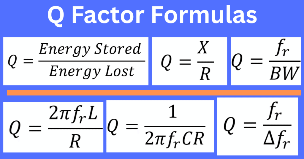
The Q factor helps quantify energy losses within components like inductors and capacitors in AC circuits. Depending on the circuit configuration, it can be expressed using multiple formulas:
- Q = (2πfL) / R → used for inductive circuits.
- Q = 1 / (2πfRC) → used for capacitive circuits.
- Q = X / R → where X is reactance, applicable to both inductive and capacitive circuits.
- Q = Pstored / Ploss → a theoretical definition expressing energy stored vs. energy lost.
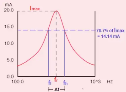
- Q = fr / Δfr → where fr is the resonant frequency and Δfr is the 3 dB bandwidth.
Comparison of Quality Factor Formulas
| Coil/Inductor | Q = (2πfL) / R | f = frequency, L = inductance |
| Capacitor | Q = 1 / (2πfRC) | f = frequency, R = resistance, C = capacitance |
| Reactance method | Q = X / R | X = reactance, R = resistance |
| Resonant Bandwidth | Q = fr / BW | fr = resonant frequency, BW = bandwidth |
| Energy Method | Q = 2π × (Stored Energy / Energy lost per cycle) | General definition |
These formulas are widely used in competitive exams like JEE, NEET, and university-level engineering.
Is Q Factor Dimensionless?
The Q factor is dimensionless, as it represents a ratio of stored energy to energy dissipated per cycle.
- Dimensional formula of Quality Factor = None
- Units = None (pure number)
Resonant Frequency and Quality Factor
The resonance in an electrical circuit occurs at a particular frequency, which is called the resonant frequency. AC circuits generally have inductors and capacitors. The reactance of the capacitor and inductor become equal at a specific frequency, and their reactance cancels out. The frequency at which this condition occurs, the circuit is said to be in resonance. Thus, at resonance, all the impedances or admittances cancel each other out, and the circuit behaves like a resistive circuit. The voltage and current of a resonant circuit are in the same phase.
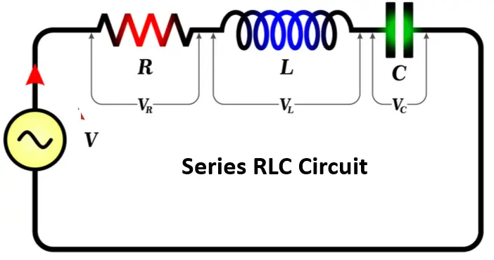
In the case of an RLC circuit, we can find the resonance frequency by equating the inductive and capacitive impedances, which cancel each other out.
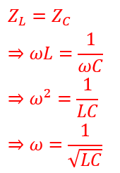
Since,
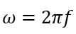
The resonance frequency of the series RLC circuit is;
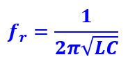
fr = 1 / (2π√(LC))
Relationship Between Quality Factor and Resonant Frequency
In AC circuits, especially those with inductors and capacitors, the Quality Factor (Q) and resonant frequency (fr) are directly related. While fr represents the frequency at which the circuit naturally oscillates with maximum energy transfer, Q indicates how sharply the circuit responds at that frequency.
The relationship is defined by the formula:
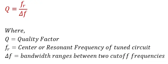
Q = fr / Δf
Where:
- Q = Quality Factor
- fr = Resonant Frequency (Hz)
- Δf = Bandwidth (Hz)
A higher Q means a narrower bandwidth around fr, indicating sharper resonance and lower energy loss. This is essential in tuning circuits, filters, and oscillators where frequency precision and selectivity are critical.
Effects of Q Factor on Circuit Parameters
A high value of the Quality factor is always desirable with RF-tuned circuits. However, in some applications, a defined level of Q may be required. The Q factor affects the following parameters of the tuned circuit.
Bandwidth
The bandwidth of the tuned circuit filter reduces with an increase in the Quality factor as losses decrease. The high energy storage in an inductor or capacitor causes a tuned circuit to have a sharper bandwidth.
With a higher Q, the 3 dB bandwidth becomes narrower, improving selectivity.
General Spurious Signals
Tuned circuits and filters can remove spurious signals better with sharper filters and higher Q levels.
Oscillator Phase Noise
Every oscillator produces phase noise. The phase noise is random fluctuations in the phase of the signal. This results in additional undesirable noise that spreads out from the main carrier.
Higher Q circuits reduce phase noise in oscillators.
Ringing
As the Q factor of a resonant circuit increases, circuit losses decrease. This increases the decay time of oscillations, making the circuit ring more. This is Ideal for oscillator circuits, as lower energy loss helps sustain oscillations effectively.
Q Factor and Damping Behavior
A critical aspect of many circuits is damping, determined by the Quality Factor (Q). It affects how damped oscillators and other circuits, such as filters, respond to signals. Based on the value of Q, the system’s response can be classified into three categories:
Under-damped (Q > 1/2)
A system is under-damped when the Quality Factor (Q) is greater than 0.5. If Q is only slightly above this threshold, the system may oscillate once or twice before stabilizing.
As Q increases, damping decreases, and oscillations persist longer. In an ideal case with infinite Q, oscillations would continue indefinitely without external input.
A higher Q typically results in cleaner signals with reduced phase noise.
Over-damped (Q < 1/2)
An over-damped system is characterized by a Quality Factor (Q) less than 0.5. In this condition, losses are high and there’s no overshoot. The system decays exponentially and gradually approaches its steady-state value after a step impulse.
As Q decreases further, the response becomes increasingly slow and sluggish.
Critically damped (Q = 1/2) :
A critically damped system has a Q factor of 0.5. Like the over-damped case, it does not oscillate or overshoot. However, it reaches the steady-state value as quickly as possible without oscillation, making it ideal for fast and stable responses.
Application Considerations
In RF resonant systems, a high Quality factor is often required for improved frequency selectivity and reduced phase noise. For filters, sufficient Q ensures desired bandwidth without excessive sharpness. In oscillators, high Q results in greater frequency stability. However, if Q is too high, filters may become too narrow, and oscillators may lose the ability to track over the required range.
Generally, a high Q is preferred—but it must be optimized for the specific application.
Conclusion
The Quality Factor is a key indicator of how efficiently a circuit stores energy with minimal loss. A higher Q implies sharper frequency selectivity and lower energy dissipation, making it ideal for precision applications like filters, oscillators, and RF tuning circuits.
However, a very high Q isn’t always better. In some cases, it leads to overly narrow bandwidth, which can restrict performance in wideband or dynamic systems. That’s why the Q factor must be carefully chosen based on specific circuit needs.
When optimized, it improves signal clarity, phase noise performance, and resonance control—contributing to better circuit efficiency and reliability.
Understanding the Q factor allows engineers to fine-tune energy behavior, match application demands, and build more effective electronic systems.
FAQs
Use Q = (2πfL) / R for coils, or Q = fr / BW for resonance bandwidth.
Q is dimensionless; it has no units or dimensional formula.
It indicates how efficiently the coil stores energy versus how much it loses to resistance. Higher Q means lower energy loss.
Q = fr / BW — higher Q results in narrower bandwidth.
Read Next: