An induction type wattmeter is an electrical measuring instrument used to measure active power in alternating current (AC) circuits. It operates on the principle of electromagnetic induction, in which alternating magnetic fluxes induce eddy currents in a conducting disc. The interaction between these fluxes and the induced currents produces the torque required for power measurement.
A wattmeter determine the actual power consumed by an electrical load, while an induction type wattmeter performs this measurement using an electromagnetic mechanism. It is suitable only for AC circuits because its operation depends on alternating magnetic flux.
In this article, you will learn about the construction of an induction type wattmeter, its working principle, torque equation, advantages, disadvantages, and differences between induction type and electrodynamometer wattmeters.
Construction of an Induction Type Wattmeter
An induction type wattmeter consists of two electromagnets, a lightweight aluminium disc, a spindle, a pointer, a calibrated scale, and a controlling mechanism. The two electromagnets produce the magnetic fluxes required to generate the driving torque.
An induction type wattmeter circuit diagram is shown in the image below.
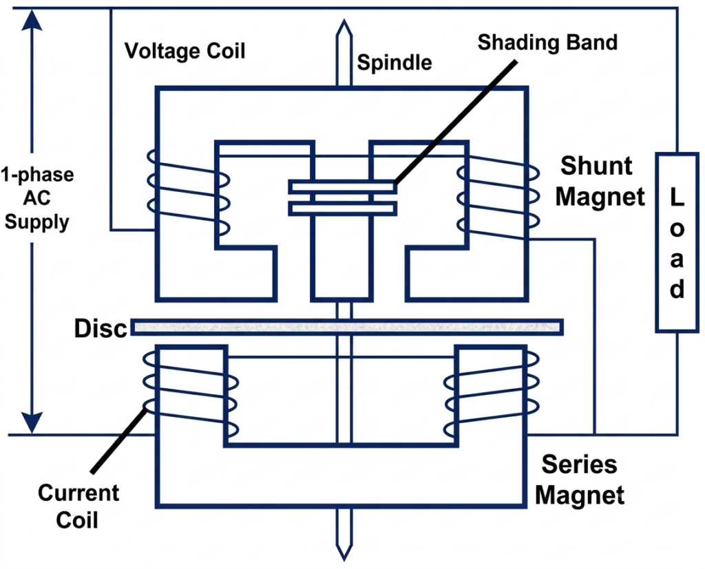
The main components are described below.
1. Shunt Magnet (Voltage Magnet)
The shunt magnet is constructed from laminated silicon steel and is connected across the load through its voltage coils. These coils consist of many turns of fine wire and carry a small current proportional to the supply voltage.
The shunt magnet produces a magnetic flux proportional to the applied voltage. Shading bands are fitted to the appropriate part of the magnetic circuit to adjust the phase of this flux.
For correct operation, the shunt flux is designed to lag the supply voltage by approximately 90 degrees.
2. Series Magnet (Current Magnet)
The series magnet is also made of laminated silicon steel. It carries the current coils, which are connected in series with the load.
The current coils consist of relatively few turns of thick wire because they carry the load current. The magnetic flux produced by the series magnet is approximately proportional to the load current.
The interaction between the flux produced by the series magnet and the flux produced by the shunt magnet generates the driving torque.
3. Aluminium Disc
A thin, lightweight aluminium disc is mounted on a spindle and positioned in the air gap between the two magnetic systems.
When the alternating magnetic fluxes pass through the disc, they induce eddy currents in it. The interaction between the induced currents and the magnetic fluxes produces the driving torque that causes the disc to rotate.
4. Spindle and Pointer
The aluminium disc is attached to a spindle that transmits its movement to the indicating mechanism. A pointer connected to the spindle moves over a calibrated scale to indicate the measured power.
5. Controlling Mechanism
A controlling mechanism provides an opposing torque to balance the driving torque and establish the final pointer position. In an indicating induction wattmeter, this is commonly achieved using a spring arrangement.
6. Damping Mechanism
The damping mechanism reduces unwanted oscillations of the moving system and helps the pointer settle at its final reading. Its design depends on the particular instrument.
Working Principle of an Induction Type Wattmeter
An induction type wattmeter works on the principle of electromagnetic induction and the interaction of magnetic fluxes with eddy currents.
The operation involves the following steps.
Step 1: Production of Magnetic Fluxes
When the wattmeter is connected to an AC circuit, the voltage coils of the shunt magnet produce a flux related to the supply voltage. At the same time, the current coils of the series magnet produce a flux related to the load current.
The two fluxes have a phase relationship determined by the circuit power factor and the design of the wattmeter.
Step 2: Induction of Eddy Currents
The alternating magnetic fluxes pass through the aluminium disc and induce eddy currents in it. These currents flow within the conducting material of the disc.
The magnitude and phase of the induced currents depend on the magnetic fluxes, the disc’s electrical properties, and the operating frequency.
Step 3: Production of Driving Torque
The induced eddy currents interact with the magnetic fluxes produced by the two electromagnets. This interaction generates a driving torque on the aluminium disc.
Under the intended operating conditions, the average driving torque is proportional to the active power in the circuit.
Step 4: Pointer Deflection
The driving torque moves the disc, spindle, and pointer against the controlling torque. The pointer settles at a position corresponding to the power being measured.
The calibrated scale indicates the active power in watts or kilowatts.
Torque Equation of an Induction Type Wattmeter
The torque equation explains how the interaction of magnetic fluxes produces a deflecting torque proportional to active power.
Let:
- = RMS supply voltage
- = RMS load current
- = Phase angle between voltage and current
- ) = Magnetic flux produced by the shunt magnet
- = Magnetic flux produced by the series magnet
- = Average driving torque
- Esh = Emf induced in the disc by the shunt magnet flux
- Ish = Eddycurrent in the disc caused by emf Esh
- Ese = Emf induced in the disc by the series magnet flux
- Ise = Eddycurrent in the disc caused by emf Ese
The following phasor diagram illustrates the phase relationship between the supply voltage, load current, shunt flux, and series flux in an induction type wattmeter.
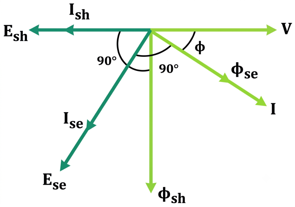
Assuming the aluminium disc is purely resistive, the induced eddy currents are in phase with their respective induced EMFs.
The series flux induces an EMF in the disc. This EMF lags the series flux by 90°. Consequently, the eddy current also lags the series flux by 90°. Since the series flux is approximately in phase with the load current , the eddy current also lags the load current by approximately 90°.
Similarly, the shunt flux induces an EMF in the disc, which lags the shunt flux by 90°. The resulting eddy current is in phase with this EMF and therefore lags the shunt flux by 90°.
1. Relationship Between the Fluxes
The shunt magnet produces a flux approximately proportional to the supply voltage:
The series magnet produces a flux approximately proportional to the load current:
The shunt flux is adjusted to lag the supply voltage by approximately 90 degrees. The series flux is approximately in phase with the load current, subject to the magnetic circuit’s characteristics.
2. Driving Torque
For the intended operating conditions, the average driving torque is proportional to the product of the two fluxes and the sine of the angle between them:
Here , is the phase angle between the two magnetic fluxes.
Since the shunt flux lags the voltage by approximately 90 degrees, the sine term becomes proportional to the cosine of the load power-factor angle:
Therefore,
Substituting the relationships between flux, voltage, and current gives:
The active power in an AC circuit is:
Hence, the driving torque is proportional to the active power:
This relationship is the fundamental operating principle of an induction type wattmeter. It assumes that the fluxes and their phase relationships behave as intended and that operating conditions remain within the instrument’s specified range.
Advantages of an Induction Type Wattmeter
Induction type wattmeters offer several advantages in suitable AC measurement applications.
- Uniform scale: The scale can be designed to provide a useful relationship between pointer deflection and measured power.
- Good damping: A suitable damping arrangement helps the pointer settle quickly.
- Robust construction: The instrument can provide reliable service when properly installed and maintained.
- Direct power indication: The pointer displays the measured power without requiring separate voltage and current calculations.
- AC power measurement: It is suitable for measuring active power in AC circuits within its specified operating conditions.
Disadvantages of an Induction Type Wattmeter
Despite its advantages, an induction type wattmeter has several limitations.
- AC operation only: It cannot measure steady DC power because its operating principle requires alternating magnetic flux.
- Frequency dependence: Changes in supply frequency can affect the flux phase relationships and measurement accuracy.
- Temperature effects: Changes in coil resistance and other instrument properties can introduce measurement errors.
- External magnetic fields: Stray magnetic fields may influence the operation of the instrument.
- Mechanical limitations: The moving disc, spindle, and indicating mechanism may be affected by friction, wear, and vibration.
- Power consumption: The voltage and current circuits consume some power during measurement.
Difference Between Electrodynamometer and Induction Type Wattmeters
Both instruments measure electrical power, but they operate using different principles and have different construction arrangements.
| Parameter | Electrodynamometer Wattmeter | Induction Type Wattmeter |
| Working principle | Interaction between magnetic fields of fixed and moving coils | Electromagnetic induction and interaction with eddy currents |
| Supply type | AC and DC | AC only |
| Moving component | Moving coil and pointer | Aluminium disc, spindle, and pointer |
| Current circuit | Fixed current coil or coils | Series magnet with current coils |
| Voltage circuit | Moving pressure coil | Shunt magnet with voltage coils |
| Frequency dependence | Suitable for AC measurements within its specified frequency range; also works on DC | Depends on alternating flux and its phase relationships |
| Damping | Commonly air-friction damping | Depends on the instrument’s damping arrangement |
| Typical application | Laboratory power measurements and instrument calibration | Specialized AC power measurement |
Conclusion
An induction type wattmeter measures active power in AC circuits using electromagnetic induction. Its shunt and series magnets produce alternating magnetic fluxes that induce eddy currents in an aluminium disc. The interaction between these fluxes and currents generates the driving torque required for power measurement.
The torque equation demonstrates that the average driving torque is proportional to the active power consumed by the load, under the instrument’s intended operating conditions. Understanding its construction, working principle, and torque equation helps explain how electromagnetic instruments measure AC power.
Read Next:
- Types of Energy Meters and Their Working Principles
- Three Phase Energy Meter Connection Diagram
- Calculation of Multiplication Factor of Energy Meters
- Clamp Meter Working Principle, Diagram & Uses
- Single Phase Energy Meter Calibration
- Single Phase Energy Meter: Construction, Working Principle, Types
- Single Phase Energy Meter Connection Diagram: Wiring, Terminals
- Wattmeter: Working Principle, Types, Advantages, and Applications