Open-circuit and Short-Circuit Tests of transformers are carried out to assess core losses, magnetizing current, impedance, and copper losses. These tests provide essential insights into transformer efficiency, performance, and operational reliability, ensuring optimal functionality within electrical power systems.
Open Circuit Test on Transformer
The Open Circuit Test, also known as the No-Load Test, is performed on a transformer to measure the core losses (also referred to as iron losses) and to determine parameters related to the magnetizing component of the current. When energized, core losses include hysteresis and eddy current losses in the transformer’s core. This test is conducted with the secondary winding open-circuited, meaning no load is connected to the secondary side.
The Open Circuit Test provides valuable information about core losses, magnetizing current, and shunt parameters. Core losses occur constantly whenever the transformer is energized, regardless of the load. They are crucial for determining the transformer’s efficiency. The magnetizing current is required to establish the magnetic field in the transformer’s core. Shunt parameters include the core loss resistance (R0) and magnetizing reactance (X0).
To meet the plant load requirement when cpp power is not available is possible now.
The procedure of the Open Circuit Test
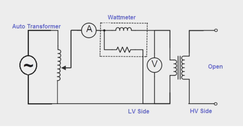
For safety and convenience, the open circuit test is typically performed on the transformer’s low-voltage (LV) side. First, ensure the transformer is de-energized and properly isolated from the power supply. Connect the necessary measuring instruments, such as a voltmeter, ammeter, and wattmeter, to the LV side of the transformer. The secondary side (high-voltage side) should remain open-circuited.
Next, the rated voltage is applied to the primary winding (LV side). The secondary winding remains open-circuited throughout the test. Record the readings of the voltmeter (V1), ammeter (I0), and wattmeter (W0). The voltmeter measures the applied voltage (V1), the ammeter measures the no-load current (I0), and the wattmeter measures the power consumed (W0), which represents the core losses.
Based on the measurements obtained, we can calculate the following parameters:”
The power reading from the wattmeter directly gives the core losses. The current measured by the ammeter is the transformer’s no-load current (I0).
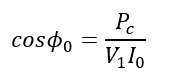
The power factor during the no-load condition can be calculated as:

V1= Voltage reading by the voltmeter
I0= The no-load current
Pc= Power reading of Wattmeter
The no-load power factor is
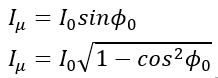
The magnetizing current(Iμ) is.
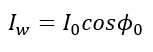
The core loss current(Iw) is,
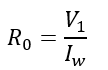
The Core Loss Resistance(R0) is,
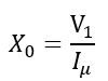
The magnetizing reactance(X0) is.
Short Circuit Test on Transformer
The Short Circuit Test, or the Full-Load Test, is performed on a transformer to determine its series parameters and copper losses. Copper losses, also known as winding losses or I²R losses, occur due to the resistance of the transformer windings when current flows through them. This test is conducted with the secondary winding short-circuited and a reduced voltage applied to the primary winding.
The Short Circuit Test provides essential information about the transformer’s impedance, vital for understanding voltage regulation and fault analysis. It also determines the copper losses, which are directly related to the efficiency of the transformer under load conditions. By knowing these parameters, engineers can predict the transformer’s performance under various operating conditions and ensure it operates efficiently and reliably.
The procedure of the Short Circuit Test
The Short Circuit Test is typically performed on the transformer’s high-voltage (HV) side to minimize the current required for the test. The first step is to ensure the transformer is de-energized and properly isolated from the power supply. Then, the necessary measuring instruments, such as a voltmeter, ammeter, and wattmeter, are connected to the HV side of the transformer. At the same time, the secondary side (low-voltage side) is short-circuited.
The short-circuit test circuit diagram is displayed below for your reference.
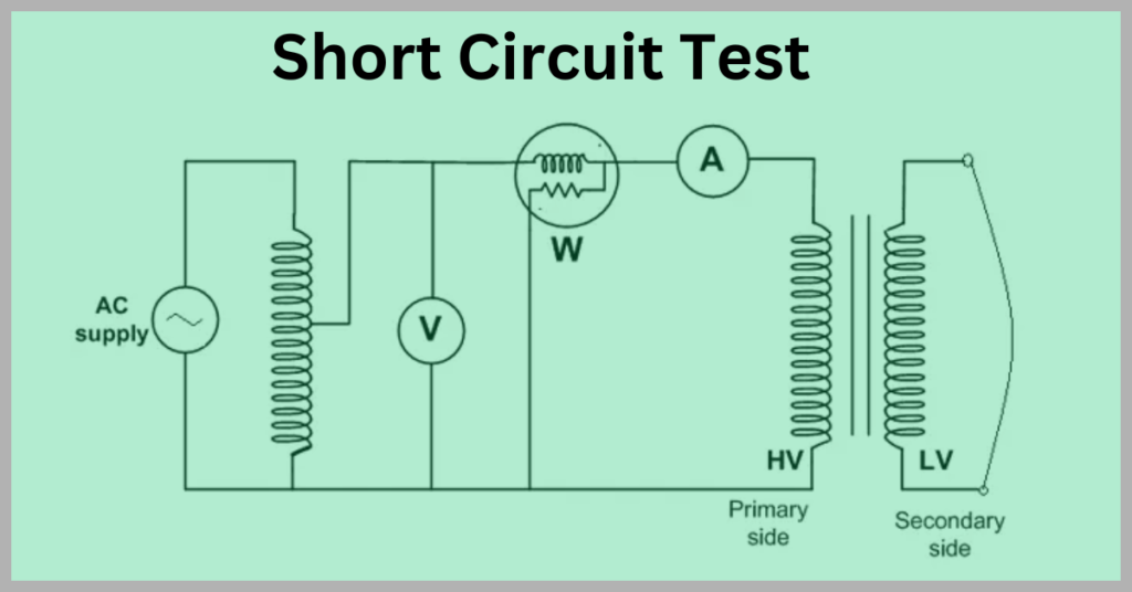
Next, a reduced voltage is gradually applied to the primary winding (HV side) until the rated current flows in the windings. The voltage applied is usually much lower than the transformer’s rated voltage since the secondary winding is short-circuited. During the test, the voltmeter measures the applied voltage (Vsc), the ammeter measures the short-circuit current (Isc), and the wattmeter measures the power consumed (Wsc), representing the copper losses.
The power reading from the wattmeter directly gives the copper losses:
The voltage measured by the voltmeter is short circuit voltage (Vsc). The current measured by the ammeter is the short circuit current (Isc).
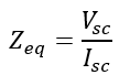
The equivalent impedance of the transformer can be calculated as:
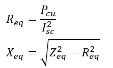
The equivalent resistance and reactance can be derived from the copper losses and impedance:
Conclusion
The Open Circuit and Short Circuit Tests evaluate key parameters such as core losses, magnetizing current, impedance, and copper losses. These tests provide transformer efficiency and performance data, which can accurately model and analyze behavior under various conditions.
Related Articles: