A capacitive voltage transformer (CVT) is a device used to measure high voltage in electrical power systems. It steps down the high voltage to a lower voltage level suitable for measuring and protecting relays.
It has three main parts that reduce the voltage: the potential divider, inductive element, and auxiliary transformer.
As you know, the conventional potential transformer can step down the high-voltage to the desired level. Nevertheless, CVTs are used for the same function.
Reasons for the use of CVT
The inductive transformer needs more insulation to measure high voltage. In CVT, the high voltage is reduced in two steps: In the first step, the capacitive divider circuit steps down the voltage, and in the second stage, the auxiliary transformer decreases the voltage. Thus, the insulation requirement for the auxiliary transformer is reduced, and hence, the cost of CVT is reduced. Like conventional transformers, the CVT provides galvanic isolation as well.
Thus, the capacitive voltage transformer is more economical and safer for high-voltage measurement.
Circuit Diagram of Capacitive Voltage Transformer
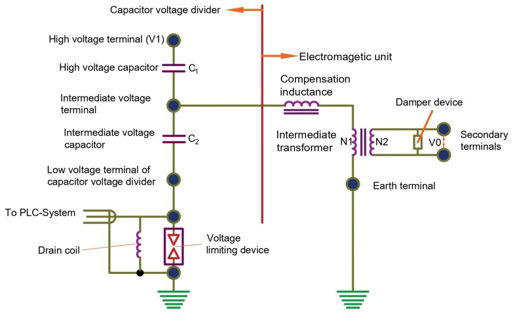
Circuit Description: The primary high-voltage line is connected to the capacitive voltage divider. The series capacitors C1 and C2 divide the high voltage to the intermediate level. The voltage across the lower capacitor C2 is fed to the transformer. The transformer steps down the intermediate voltage to a lower level, and the output terminals provide the low voltage for measurement, protection, and communication purposes.
Capacitive Voltage Transformer Working
The working principle of a Capacitive Voltage Transformer (CVT) is based on voltage division using capacitors and a step-down transformer. The CVT has two capacitors connected in series and forms a capacitive voltage divider. The voltage rating of individual capacitors is small; therefore, several smaller capacitors are connected in series to handle high voltage. The high voltage is applied across the series of capacitors. Capacitors C1 and C2 form a voltage divider circuit, and reduced voltage is obtained across the capacitor C2 due to the capacitive voltage division principle.
The voltage obtained across capacitor C2 can not be fed to meters or protection relays, and this voltage level, which we can call the intermediate voltage level, needs to be further reduced. The intermediate voltage is then fed to a step-down transformer. The primary winding of the step-down transformer receives the intermediate voltage. The transformer steps down this voltage to a much lower, standard secondary voltage level suitable for measurement and instrumentation.
The energy meters and protection relays are resistive loads, and the voltage divider circuit of the CVT is a capacitive load. The difference in the nature of the load creates a phase shift, and to mitigate this issue, inductance is connected in the series of primary windings of the transformer.
The output of CVT can be expressed by the following formula.
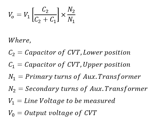
The capacitance value of C1 is higher than that of C2, so the value of C1/(C1+C2) is small. Thus, the output voltage of CVT mainly depends on the transformer’s turn ratio, which means the voltage transformation ratio of the capacitive potential transformer is free from burden.
Conclusion
A Capacitive Voltage Transformer (CVT) is an important and essential component in high-voltage power systems. It provides several advantages, such as cost-effectiveness, reduced size and weight, and high measurement accuracy. CVTs can safely and accurately step down high voltages to manageable levels for metering and protection. Additionally, CVTs facilitate power line carrier communication.
- Transformer Core Saturation
- What is a step-up Transformer?
- Turn ratio and voltage ratio of the transformer