LV and HV winding in transformer are essential components that enable voltage transformation in electrical power systems. These windings handle different voltage and current levels and are carefully placed to optimize performance, safety, and insulation.
One commonly asked question is: Why is the LV winding placed near the core while the HV winding is outside?
In this article, we’ll explore everything about LV and HV winding in transformer—from their full forms and construction to their functions, placement, and practical design advantages.
What is LV and HV in a Transformer?
In electrical engineering:
- HV stands for High Voltage
- LV stands for Low Voltage
These classifications help identify voltage ranges used in different applications:
- Low Voltage (LV): Ranges from 0V to 1,000V AC (or up to 1,500V DC). It is commonly used in homes, offices, and small industries.
- High Voltage (HV): Typically refers to voltages above 1,000V AC. It is used in transmission lines, substations, and heavy industrial systems.
In transformers, these terms indicate the side connected to either the power grid (HV) or the electrical load (LV).
What Are HV and LV Windings in Transformer?
A transformer has two main sets of windings wrapped around a magnetic core:
- LV Winding – Full form: Low Voltage Winding
- HV Winding – Full form: High Voltage Winding
These windings are electrically insulated from each other and the core. The LV winding is designed to carry low voltage and high current, while the HV winding handles high voltage and low current.
Understanding the LV and HV winding full form is essential when reading transformer schematics, labeling terminals, or working with power systems.
These windings are responsible for managing the current and voltage relationship in both step-up and step-down transformers, depending on whether the transformer is increasing or decreasing the voltage level.
Construction of HV and LV Windings
The construction of transformer windings depends on the voltage rating, current capacity, and performance needs. The two most common winding arrangements are:
1. Concentric Windings
In this arrangement:
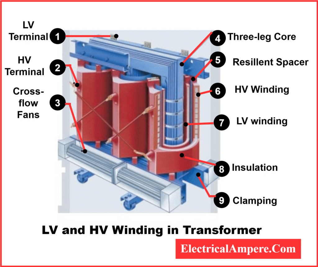
- The LV winding is placed closest to the core
- The HV winding is wound over the LV winding
Interleaved winding is a special arrangement where HV and LV windings are alternately placed in layers. This technique:
- Reduces leakage reactance
- Improves coupling between the windings
- Enhances voltage regulation
It is commonly used in high-performance transformers like those in power electronics or audio systems.
The layout is optimized to manage the current and voltage relationship—with LV windings carrying high current and low voltage, while HV windings handle high voltage and low current.
2. Sandwich or Interleaved Windings
This type alternates layers of HV and LV windings. It is usually used in distribution transformers to:
- Reduce leakage reactance
- Improve voltage regulation
- Enhance overall magnetic coupling
Difference Between HV and LV Side of a Transformer
Each transformer has two defined sides:
- HV Side (High Voltage Side): This is connected to the incoming power supply, such as a substation or transmission line.
- LV Side (Low Voltage Side): This connects to the load, like a residential area, commercial building, or machinery.
Correctly identifying the HV and LV sides ensures safe installation and efficient transformer operation
Why LV Winding Is Placed Near the Core?
The LV winding is placed closest to the core for the following key reasons:
- Better Insulation Management:
Placing the high-voltage (HV) winding outside helps in easier insulation from the low-voltage winding and the grounded core. - Cost-Effective Design:
The inner winding (LV) requires less insulation since it operates at lower voltage. This saves both cost and space. - Mechanical Stability:
It provides better mechanical support during short-circuit conditions due to the core’s proximity. - Heat Dissipation Efficiency:
Since LV windings carry higher current, placing them near the core enhances cooling through the core structure.
How to Identify LV and HV Winding of Transformer?
Identifying the LV (Low Voltage) and HV (High Voltage) windings is crucial during transformer installation or maintenance. Here’s how to distinguish them:
- 1. Number of Turns and Wire Thickness:
- HV winding has more turns of thinner wire.
- LV winding has fewer turns of thicker wire.
- 2. Position:
- LV winding is placed near the core.
- HV winding is wound over the LV winding.
- 3. Insulation:
- HV winding has thicker insulation due to high voltage.
- LV winding requires less insulation.
- 4. Terminal Markings:
- HV terminals are usually marked H1, H2, etc.
- LV terminals are labeled X1, X2, etc.
- 5. Connected Side:
- The HV side connects to the grid or source.
- The LV side connects to the electrical load.
Quick Summary- LV and HV Winding
| Feature | LV Winding | HV Winding |
| Full Form | Low Voltage Winding | High Voltage Winding |
| Placement | Near the core | Outside the LV winding |
| Handles | High current, low voltage | Low current, high voltage |
| Insulation Requirement | Low | High |
| Connected Side | Load side (homes, industry) | Supply side (grid, transmission) |
Conclusion
Understanding the role and placement of HV and LV windings in a transformer helps in both design and application.
The LV winding is placed near the core to minimize insulation requirements, enhance mechanical stability, and reduce cost. The HV winding, dealing with high voltages, is placed farther for safety and insulation ease,
Related Articles:
- Difference Between Step Up and Step Down Transformer
- Single Phase Transformer: Working, Diagram, Applications
- Parallel Operation of Transformers
- Booster Transformer
- Why is the Core of a Power Transformer Grounded?
- Parts of the Transformer and their Functions
- Potential Transformer: Definition, Working, Types, Diagram & Applications