Learn everything about the Parallel Operation of Transformer — its principles, requirements, advantages, disadvantages, and important considerations for efficient and reliable power system performance.
What is Parallel Operation of Transformer?
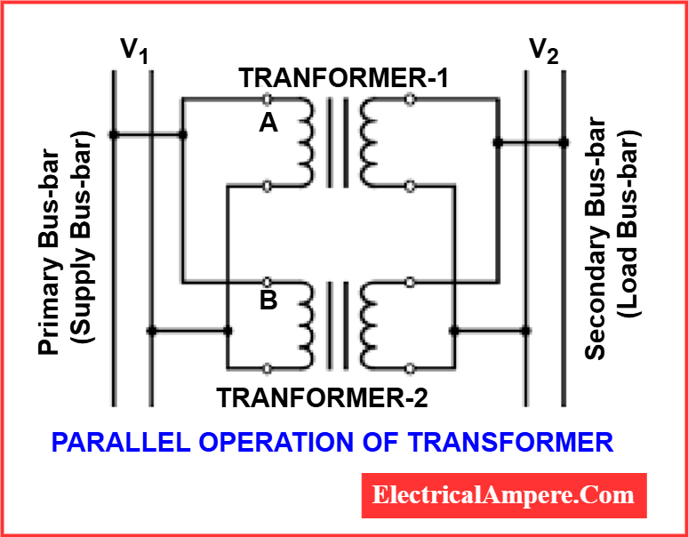
Parallel operation of transformers refers to the process of connecting two or more transformers to a common busbar on both the primary and secondary sides so they operate together to supply a common load.
In this setup, all the transformers share the total load current, allowing them to function as a single larger transformer while maintaining flexibility and reliability.
Why Parallel Operation of Transformers is required?
When the load demand exceeds the capacity of an existing transformer, it is often more practical to connect another transformer in parallel rather than replacing the original unit with a larger one. This parallel operation of transformer setup not only meets the increased load but also enhances system reliability and flexibility.
Transformers in parallel operation are particularly beneficial when the load on a single transformer surpasses its rated capacity. In such cases, connecting two or more transformers in parallel allows for effective load sharing. Additionally, the transformer parallel operation reduces the cost of maintaining spares. For instance, keeping a spare unit for two identical parallel transformers is generally more economical than maintaining a spare for a single, larger unit.
From a reliability perspective, parallel operation of transformers ensures continuity of supply. If one transformer is taken out of service for maintenance or due to a fault, the other unit can still supply at least part of the load. This redundancy is a key advantage of parallel operation of single phase transformers or three-phase units, especially in critical applications.
Conditions for Parallel Operation of Transformers
In the parallel operation of transformer systems, the primary windings of each transformer are connected to the source bus-bars, while the secondary windings are connected to the load bus-bars. This setup enables transformers to share the load efficiently and improve system reliability. However, for transformers in parallel operation to work effectively and safely, several critical conditions must be met.
Essential Conditions for Parallel Operation of Transformers:
- Same Voltage Ratio and Turns Ratio
Both the primary and secondary voltage ratings should be identical. A mismatch may cause circulating currents and uneven load sharing. - Same Percentage Impedance and X/R Ratio
This ensures proper load sharing in proportion to their ratings. A difference can lead to overloading one transformer and underutilizing the other. - Identical Tap Changer Position
Tap positions must be set identically on each transformer to maintain voltage balance. - Same kVA Ratings
While not mandatory, using transformers with equal ratings simplifies load division and minimizes circulating currents. - Same Phase Angle Shift (Identical Vector Group)
The vector group determines the phase displacement between primary and secondary. Transformers with different vector groups cannot operate in parallel. - Same Frequency Rating
Both transformers must be designed for the same system frequency to ensure synchronism. - Same Polarity
Proper polarity alignment avoids short-circuit conditions during transformer parallel operation. - Same Phase Sequence
Especially important in parallel operation of single phase transformers within a three-phase system to prevent faults.
Mandatory vs. Convenient Conditions of Parallel Operation
Some conditions for parallel operation of transformers are mandatory, while others are convenient for optimal performance:
- Mandatory Conditions:
Same phase angle shift, same polarity, same phase sequence, and same frequency. These must be strictly followed to prevent damage and malfunction. - Convenient Conditions:
Same voltage ratio, turns ratio, percentage impedance, identical kVA ratings, and tap changer position. These help in balanced load sharing and efficiency but do not prevent transformers in parallel operation.
When these convenient conditions are not fully met, parallel operation of single phase transformer or three-phase transformers is still possible—but it may lead to inefficiencies like circulating currents or unbalanced load sharing.
1). Same Voltage Ratio and Turns Ratio (on Each Tap)
One of the critical conditions for parallel operation of transformers is having the same voltage ratio and turns ratio across all tap settings. When transformers in parallel operation have even a slight mismatch in their voltage ratios, it leads to undesirable effects—particularly the flow of circulating currents.
Under no-load conditions, if the voltage ratios differ, the induced EMFs in the secondary windings won’t be equal. This inequality creates a closed loop between the secondaries, allowing a circulating current to flow. Because transformer leakage impedance is relatively low, even a minor voltage difference can result in a large circulating current—much higher than the typical no-load current.
When the system is under load, this circulating current persists and causes unequal load sharing. One of the transformers may end up overloaded, while the other remains underutilized. This not only reduces efficiency but can also compromise the reliability and safety of the transformer parallel operation.
In the case where two transformers with different voltage ratios are connected in parallel to the same primary voltage source, their secondary voltages will naturally differ. When these secondaries are tied together at a common bus, the mismatch causes a circulating current between them. And since transformer internal impedance is low, even this small voltage difference can cause a large current to circulate, leading to extra I²R losses and heating.
To avoid this issue, both the primary and secondary windings of the transformers must have identical voltage ratings. This means they must have the same transformation ratio (turns ratio). Maintaining this equality is essential for ensuring a safe and efficient parallel operation of transformer systems.
This principle is especially critical in parallel operation of single phase transformers, where any imbalance can quickly lead to system inefficiency or failure.
2). Same Percentage Impedance and X/R Ratio
Another vital condition for the parallel operation of transformers is that all units must have the same percentage impedance and X/R ratio. This ensures proper load sharing and avoids issues like unbalanced loading or reduced system efficiency.
In an ideal scenario, if transformers in parallel operation have the same per unit (percentage) impedance, they will naturally share the load in proportion to their KVA ratings. However, there’s an important nuance—two transformers may have equal per unit impedances but different X/R ratios (reactance-to-resistance ratios). This causes the phase angles of their currents to differ.
As a result, one transformer will operate at a higher power factor, while the other may run at a lower power factor. Consequently, the real power (kW) will not be shared in proportion to their ratings, even if the current magnitudes are correctly proportioned. This mismatch not only affects efficiency but can also cause heating, increased losses, and potential reliability issues in the transformer parallel operation setup.
It’s also crucial to remember that the current shared by each transformer is inversely proportional to its internal impedance. So for transformers running in parallel, their impedances must be inversely proportional to their MVA ratings to ensure proportional current and power sharing. This is why it’s important that all transformers in parallel have identical percentage impedances.
In the parallel operation of single phase transformers, especially when forming three-phase transformer banks (like Y-Y connections), matching impedance becomes even more critical. Unequal impedances can cause voltage imbalance, leading to uneven loading, increased core losses, or even core saturation in the transformer with the highest magnetizing impedance.
Let’s consider an example:
When single-phase transformers with equal KVA ratings are connected in a Y-Y configuration with an isolated neutral, even a small difference in magnetizing impedance can be problematic.
Case 1: Equal Impedance, Voltage Ratios, and Same kVA Ratings
In the ideal scenario of parallel operation of transformers, the best practice is to connect units that have the same voltage ratio (turns ratio), equal percentage impedance, and identical kVA ratings. This combination ensures balanced load sharing, eliminates circulating currents, and maximizes the efficiency and reliability of the power system.
When all these parameters match, the transformers in parallel operation behave symmetrically—each unit shares the load in proportion to its rating without any internal power struggle or overloading.
Example:
Let us consider two transformers:
- Transformer 1: 2000 kVA, 5.75% impedance
- Transformer 2: 2000 kVA, 5.75% impedance
- Combined load: 4000 kVA
Since both transformers have the same kVA rating and impedance, the formula for load sharing becomes:
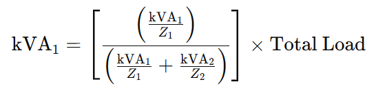
Substituting the values:
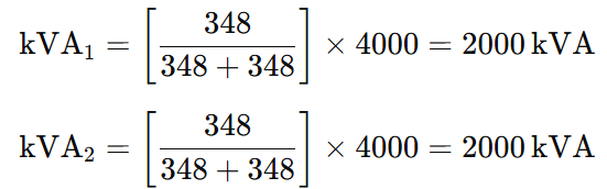
Result:
- Transformer 1 load: 2000 kVA
- Transformer 2 load: 2000 kVA
Both transformers share the load equally, confirming that when all parameters are matched, transformer parallel operation performs optimally.
This principle is applicable in both three-phase and single phase transformers parallel operation, provided all matching conditions are satisfied. It ensures that the full load can be shared efficiently without causing excessive heating, circulating currents, or operational stress.
Case 2: Equal Impedances, Equal Voltage Ratios, and Different kVA Ratings
In some scenarios of parallel operation of transformers, especially in older or retrofit systems, transformers with different kVA ratings but the same voltage ratio and equal percentage impedance are connected in parallel to a common bus. Although this setup is not commonly preferred in new installations, it is technically valid and functional.
In this case, since both transformers have the same turns ratio, there will be no circulating currents. The key point is the equal percentage impedance, which ensures that each transformer shares the load proportionally to its kVA rating.
This type of configuration is valid for both three-phase units and the parallel operation of single phase transformers, provided other essential conditions are satisfied.
Example:
Let’s consider two transformers connected in parallel:
- Transformer 1: 2500 kVA, 5.75% impedance
- Transformer 2: 1500 kVA, 5.75% impedance
- Total Load: 4000 kVA
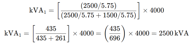
Now, compute the load shared by each transformer using the load-sharing formula for transformer parallel operation:
Loading on Transformer-1
Loading on Transformer-2
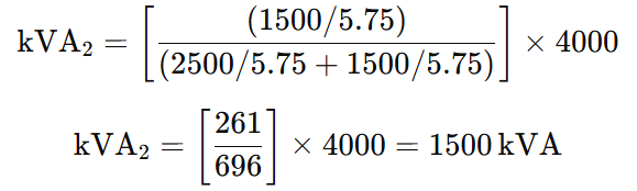
Conclusion: Each transformer carries load proportional to its rating:
- Transformer 1 = 2500 kVA
- Transformer 2 = 1500 kVA
This demonstrates that when the parallel operation of transformers maintains equal percentage impedance and identical voltage ratios, even transformers with different ratings will share the load optimally and without circulating currents.
This case is a good example of how to effectively apply the conditions for parallel operation of transformers, ensuring reliability, efficiency, and safety—especially in systems where transformers in parallel operation must accommodate varying loads.
Case 3: Unequal Impedance but Same Ratios & kVA
Mostly this parameter is used to enhance plant power capacity by connecting existing transformers in parallel that have the same kVA rating, but with different percent impedances. This is common when budget constraints limit the purchase of a new transformer with the same parameters.
It is important to understand that the current divides in inverse proportions to the impedances and larger current flows through the smaller impedance. Thus, the lower percent impedance transformer can be overloaded when subjected to heavy loading while the other higher percent impedance transformer will be lightly loaded.
Example:
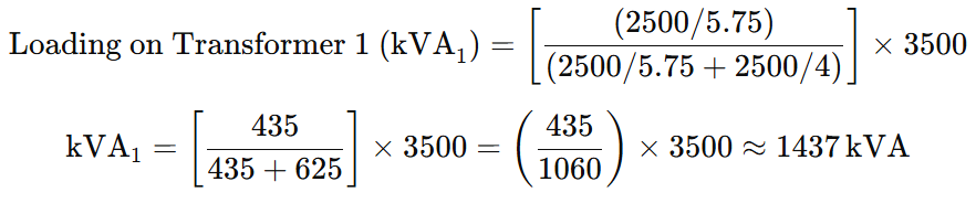
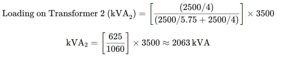
Two 2500 kVA transformers connected in parallel:
- Transformer 1: 2500 kVA, 5.75% impedance
- Transformer 2: 2500 kVA, 4% impedance
- Total Load: 3500 kVA
- Turn Ratios: Identical
Now calculate load sharing using the standard formula for parallel transformer loading:
Loading on transformer-1
Loading on transformer-2
Analysis:
- Transformer 1 (5.75% impedance) is loaded at 1437 / 2500 × 100 = 57.5%
- Transformer 2 (4% impedance) is loaded at 2063 / 2500 × 100 = 82.5%
Even though the total load of 3500 kVA is below the combined rating of 5000 kVA, the transformer with lower impedance (4%) is overloaded by 6.2% beyond the 80% safe threshold.
This clearly shows that matching percentage impedance is critical in parallel transformer operation. Unequal impedances result in imbalanced load sharing, leading to inefficiency and potential equipment stress or failure.
Case 4: Unequal Impedance and kVA – Same Voltage Ratios
This configuration is rarely used in standard industrial or commercial facilities. However, in certain exceptional scenarios, such as tying two single-ended substations together using bussing or interconnecting cables, transformers with different kVA ratings and unequal percent impedances may be paralleled to improve voltage support—for instance, when starting large motors or loads that cause temporary voltage dips.
Example-
Transformer-1: kVA1=2500kVA, %Z1=5.75%
Transformer-2: kVA2=1500kVA, %Z2=4.0%
Total load = 3500 kVA
Loading on Transformer1 :
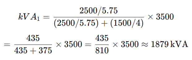
Loading on Transformer 2
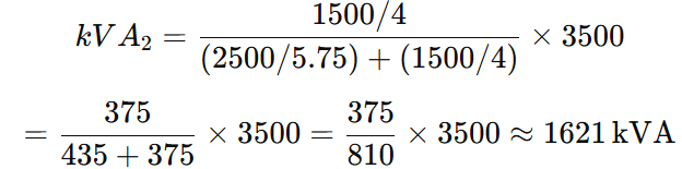
Transformer-1 carries approximately 1879 kVA, and Transformer-2 carries approximately 1621 kVA of the total 3500 kVA load.
Because the percent impedance is less in the 1500 kVA transformer, it is overloaded with a less than combined rated load.
Case 5: Equal Impedance & KVA Unequal Ratios
When two transformers with equal percent impedance but unequal kVA ratings are connected in parallel, even a small difference in their voltage settings (such as tap changer positions) can cause large circulating currents between them. This circulating current:
- Is independent of the actual load current or how the load is shared between transformers.
- Flows internally between the transformers rather than on the external supply line.
- Can cause significant overheating if the transformers are fully loaded while circulating current exists.
- Cannot be detected by monitoring equipment placed upstream or downstream of the transformer common connection point, since it flows only between the transformers.
Transformers connected in parallel must be on the same tap position to avoid circulating currents and associated overheating risks.
Example: Circulating Current in Two Paralleled Transformers
Two 3000 kVA transformers are connected in parallel, each with 4.75% impedance and the same X/R ratio of 6. Transformer 1 is tapped 2.5% above nominal voltage, while Transformer 2 is tapped at nominal voltage. Calculate the percent circulating current (%IC).
Given:
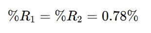
- kVA1=kVA2=3000kVA
- Percent impedance, %Z1=%Z2=4.75%
- X/R ratio = 6
- Voltage difference, %e=2.5%
- k=kVA1/kVA2=3000.3000=1
Step 1: Calculate resistance component of impedance %R
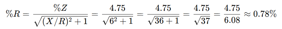
So,
Step 2: Calculate reactance component of impedance %X
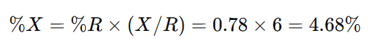
So,
Step 3: Calculate circulating current %IC
The formula for circulating current is:
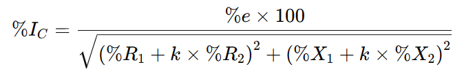
Substituting values:
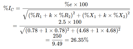
The circulating current is 26.35 per cent of the full load current.
Case 6: Unequal Impedance, KVA & Different Ratios
This situation is uncommon in practical applications. When both the transformer turns ratios and impedances differ, circulating current arises due to the unequal voltage ratios. This circulating current, combined with each transformer’s load share, determines the actual current flowing in each transformer.
- For unity power factor (PF = 1), a circulating current of 10% (caused by unequal turns ratios) results in only about 0.5% increase in the total current in each transformer.
- At lower power factors, the circulating current impact becomes much more significant, causing larger current imbalances and potential overheating.
Example:
Two transformers connected in parallel:
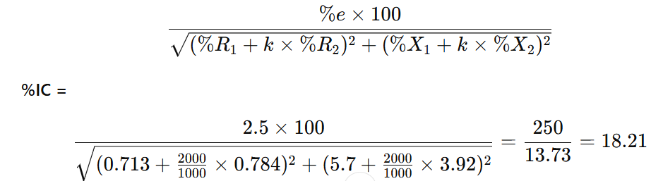
- Transformer 1: 2000 kVA, 5.75% impedance, X/R ratio = 8, tap adjusted 2.5% from nominal
- Transformer 2: 1000 kVA, 4% impedance, X/R ratio = 5, tap at nominal
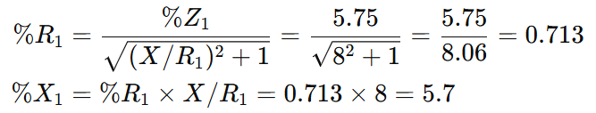
Step 1: Calculate resistive and reactive parts of impedance
Calculation of % R1 and % X1
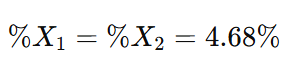
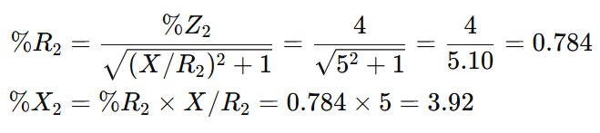
Calculation of % R2 and % X2
Step 2: Calculate circulating current %IC
3). Same Polarity
Polarity of a transformer refers to the instantaneous direction of the induced emf in the secondary winding.
- If the instantaneous directions of induced secondary emf in two transformers are opposite when the same input power is fed to both, the transformers are said to have opposite polarity.
- If connected incorrectly with opposite polarity, the secondary emfs, which are in parallel, will oppose each other and create a short circuit in the local secondary circuit.
- When transformers run in parallel, their polarity must be the same; otherwise, a large circulating current flows between the transformers, but no load will be supplied.
- If the instantaneous directions of the induced secondary emf in two transformers are the same when the same input power is fed, the transformers are said to have same polarity.
4). Same Phase Sequence
For parallel operation of three-phase transformers, the phase sequence of the line voltages of both transformers must be identical.
- If the phase sequence is incorrect, each cycle will cause short circuits between pairs of phases.
- This condition is critical and must be strictly followed to ensure safe and proper parallel operation of transformers.
5). Same Phase Angle Shift
(Zero relative phase displacement between secondary line voltages)
Transformer windings can be connected in various ways, producing different magnitudes and phase displacements in secondary voltages. These connections are grouped into distinct vector groups:
| Group | Phase Displacement | Examples |
|---|---|---|
| 1 | 0° | Yy0, Dd0, Dz0 |
| 2 | 180° | Yy6, Dd6, Dz6 |
| 3 | -30° | Yd1, Dy1, Yz1 |
| 4 | +30° | Yd11, Dy11, Yz11 |
Paralleling Rules:
- Transformers within the same group can be paralleled directly (zero relative phase displacement).
Example: Transformers with Yd1 and Dy1 connections (both Group 3) can be paralleled. - Transformers from Groups 1 and 2 can only be paralleled with transformers of their own group.
- Transformers from Groups 3 and 4 can be paralleled if the phase sequence of one transformer is reversed.
Example: A transformer with Yd11 (Group 4) can be paralleled with Dy1 (Group 3) by reversing the phase sequence of both the primary and secondary terminals of the Dy1 transformer. - To parallel Dy1 and Dy11, you can swap two phases (e.g., B & C) on both primary and secondary sides of one transformer to convert the +30° shift to -30°, making them compatible.
6). Same KVA Ratings
- When two or more transformers are connected in parallel, the load sharing between them depends on their kVA ratings.
- If transformers have the same kVA rating, they will share the load equally.
- If transformers have different kVA ratings, they share the load approximately in proportion to their ratings—provided:
- Voltage ratios are identical.
- Percentage impedances (based on their own kVA rating) are identical or very close.
- In practice, when ratings differ by more than 2:1, it is not recommended to operate those transformers permanently in parallel.
- For accurate load sharing with different ratings, transformers should:
- Have the same turns ratio.
- Have equal percentage impedances based on their respective kVA ratings.
- Have equal resistance to reactance ratios (X/R ratios).
- The circulating current in any combination of transformers should ideally not exceed 10% of the full-load rated current of the smaller transformer for satisfactory operation.
7). Same Frequency
For parallel operation of transformers, it is essential that all transformers operate at the same frequency. If transformers connected in parallel have different frequencies, it can lead to circulating currents, improper load sharing, and core saturation. Moreover, transformers are designed to operate at a specific frequency (like 50 Hz or 60 Hz). Any mismatch can cause overheating, increased losses, and potential damage to windings.
Hence, uniform frequency is a mandatory condition for safe and efficient parallel operation of transformers.
8). Identical Tap Changer Position
For the parallel operation of transformers, all transformers must have their tap changers set to the same position. Tap changers adjust the transformer’s voltage ratio to compensate for voltage drops or fluctuations. If tap positions differ among parallel transformers, it leads to unequal voltage ratios, causing:
- Circulating currents
- Unequal load sharing
- Overloading of one transformer
- Increased losses and possible damage
To ensure proper voltage matching and balanced load sharing, identical tap changer positions must be maintained across all transformers operating in parallel.
Advantages of Transformer Parallel Operation
1. Maximise Electrical System Efficiency
- Transformers usually operate at maximum efficiency near full load.
- By running multiple transformers in parallel, only the necessary number of transformers are switched on to meet the demand, allowing each to operate near full load for better efficiency.
- As load increases, additional transformers can be switched on sequentially to meet demand efficiently.
2. Maximise Electrical System Availability
- With multiple transformers running in parallel, any one transformer can be taken offline for maintenance without interrupting the power supply.
- The remaining transformers continue to supply the load, ensuring continuous power availability.
3. Maximise Power System Reliability
- If one transformer trips due to a fault, other transformers in parallel share the load.
- This reduces the risk of power interruption, provided the remaining transformers are not overloaded.
4. Maximise Electrical System Flexibility
- Parallel operation allows easy adjustment to future power demand changes.
- For increasing demand, additional transformers can be connected in parallel instead of investing in a single larger transformer, saving capital costs.
- If demand decreases, transformers can be removed or taken offline to optimize investment and operation.
Disadvantages of Transformer Parallel Operation
- Increased Short-Circuit Currents:
Parallel transformers reduce overall impedance, leading to higher short-circuit currents. This requires breakers with higher interrupting capacity. - Risk of Circulating Currents:
Differences in transformer characteristics can cause circulating currents between transformers, which reduce load capacity and increase losses. - High Bus Ratings Required:
The busbars and associated equipment must be rated for higher currents, increasing costs and complexity. - Reduced Impedance and High Fault Currents:
Parallel transformers significantly lower impedance, causing potentially damaging fault currents that may require current limiting devices such as reactors or fuses. - Complex Control and Protection:
Managing protection and control schemes for multiple transformers operating in parallel is more complicated. - Not Always Common Practice:
Due to complexity and risks, parallel operation of transformers is less commonly practiced in some industries.
Conclusion
Loading considerations for paralleling transformers are straightforward when the kVA ratings, percent impedances, and voltage ratios are identical. In such cases, equal load sharing occurs naturally among the transformers. However, when transformers have the same kVA ratings but different percent impedances, or when both kVA ratings and impedances differ, unequal load sharing will result.
Circulating currents arise primarily when the transformer turn ratios do not match, and their magnitude is influenced by the transformers’ X/R ratios. It is important to note that paralleling transformers with different vector groups, such as delta-delta and delta-wye, should be avoided due to phase displacement issues.
Read Next: