Electricity powers nearly every aspect of modern life, from household appliances to industrial machinery. But have you ever wondered what an electric circuit is, how it works, and why it is crucial in every electrical system?
Understanding circuit electricity, circuit electrical concepts, and electrical circuits and networks forms the foundation for electronics, electrical engineering, and everyday problem-solving.
In this article, we’ll explain circuit in electricity, explore types of electric circuits, their applications, and clarify the difference between electrical circuits and electrical networks.
What is an Electric Circuit in Electricity?
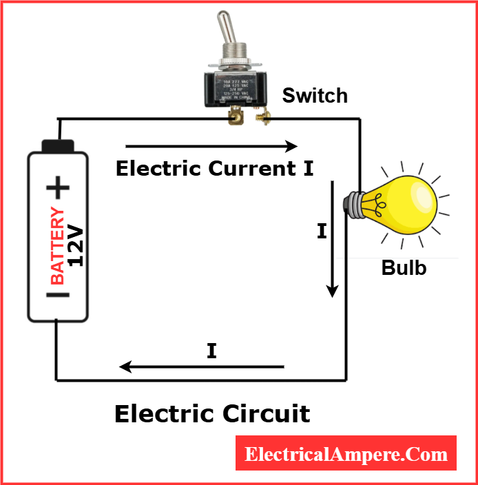
A circuit in electricity is a closed loop that allows electric current to flow from a power source, through a load, and back to the source. Think of it as a pathway for electrons to travel, delivering energy where it’s needed.
Electron Flow vs. Conventional Current:
- Electron Flow – Electrons move from the negative terminal to the positive terminal of a power source. This is the actual physical movement of charges.
- Conventional Current – By historical convention, current is considered to flow from the positive terminal to the negative terminal, opposite to electron flow. This concept is used in most circuit diagrams and engineering calculations.
Understanding the difference is important for analyzing circuits, designing electrical systems, and interpreting diagrams accurately.
Practical Example:
- Flashlight circuit – Electrons flow from the battery’s negative terminal through the bulb to the positive terminal, lighting the bulb.
- Home doorbell – Conventional current diagrams show current flowing from the positive terminal through the switch and chime back to the negative terminal.
Key points about an electric circuit:
- Requires a power source (battery or generator)
- Conductive paths (wires) connect the source to the load (bulbs, fans, or motors)
- A switch can control the flow of electricity by opening or closing the circuit
When the path is uninterrupted, the circuit is closed, and electricity flows. When the path is broken, the circuit becomes open, stopping the current.
In short, a circuit electric is a controlled environment that allows electricity to do useful work.
Types of Circuit Conditions: Open, Closed, and Short Circuits
Understanding the different conditions of an electric circuit is essential for safety and troubleshooting. Circuits can exist in three primary states:
Open Circuit
An open circuit occurs when there is a break in the electrical path, preventing current from flowing.
Example: A switch in the “off” position stops electricity from reaching a bulb.
Key Point: No current flows until the path is completed.
Closed Circuit
A closed circuit is a complete path that allows current to flow from the power source, through the load, and back to the source.
Example: Turning a switch “on” to light a lamp completes the circuit.
Key Point: Current flows uninterrupted, enabling devices to operate.
Short Circuit
A short circuit happens when two points in a circuit unintentionally connect with very low resistance, causing excessive current.
Example: Damaged wiring that allows positive and negative wires to touch can create a short circuit.
Key Point: Short circuits are dangerous and can damage devices or cause fires; protection devices like fuses or circuit breakers prevent harm.
Basic Components of an Electrical Circuit
Understanding circuit electrical components is essential for building, analyzing, and troubleshooting circuits. Each component plays a unique role in ensuring that electricity flows safely and efficiently:
A typical circuit in electricity uses the following elements to safely deliver energy from the source to the device.
- Power Source – The heart of an electric circuit, it provides the electrical energy required for current flow. Common examples include batteries, solar cells, and AC mains. The power source determines the voltage and capacity of the circuit, directly affecting the performance of connected devices.
- Conductors – These are materials that allow electric current to pass through them, typically copper or aluminum wires. Conductors form the pathway connecting the power source to the load, ensuring minimal energy loss and maintaining the circuit’s efficiency.
- Load – Any device that consumes electrical energy to perform a specific function is called a load. Examples include light bulbs, motors, heaters, and electronic gadgets. The load converts electrical energy into useful work, such as light, heat, or motion.
- Switch – A control device that can open or close the circuit. By interrupting or allowing current flow, a switch provides user control over when a device operates, enhances safety, and allows maintenance without disconnecting the power source.
- Protection Devices – Components like fuses, circuit breakers, and surge protectors safeguard the circuit from overloads, short circuits, or voltage spikes. These devices prevent damage to the load and wiring and reduce the risk of fire or electric shock.
Together, these components create a complete and functional electric circuit, allowing electricity to flow in a controlled manner to power devices efficiently and safely. Understanding each component is key for anyone working with electrical circuits and networks.
Types of Electric Circuits: Series, Parallel & Combination
Understanding types of electric circuit is crucial for designing, analyzing, and troubleshooting electrical systems. Knowing how different circuits behave helps in creating efficient, safe, and reliable electrical networks.
Electrical circuits can broadly be classified into three main types: Series, Parallel, and Series-Parallel (Combination) circuits. Let’s explore each in detail.
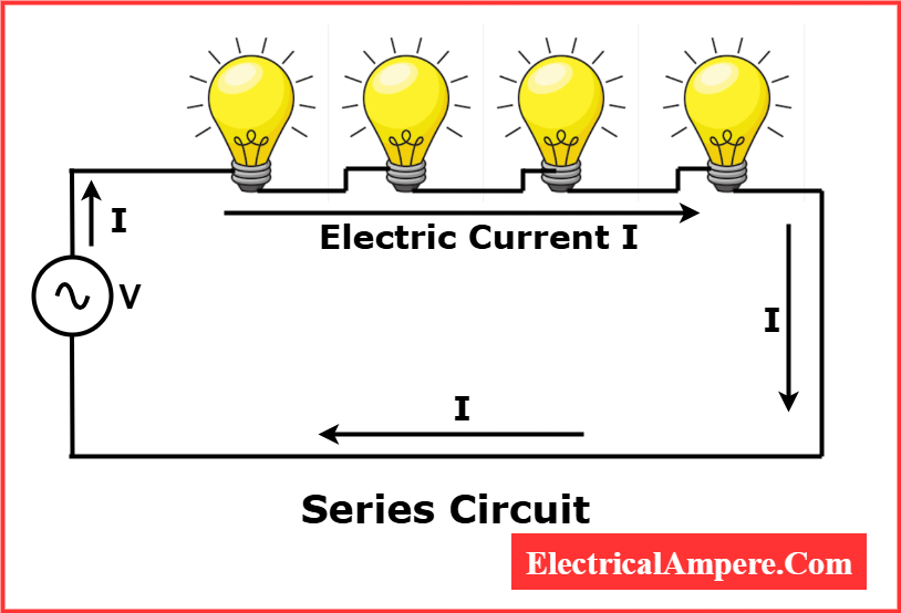
1. Series Electric Circuit – Features, Examples & Uses
A series circuit is the simplest type of electric circuit, where all components are connected end-to-end in a single path.
Key Features:
- The same current flows through all components.
- Voltage is divided among the components depending on their resistance.
- If one component fails (like a bulb burning out), the entire circuit stops working, as the path for current is broken.
Practical Examples:
- Traditional Christmas lights where one bulb going out turns off the whole string.
- Simple flashlight circuits where the battery powers a single bulb.
Advantages:
- Easy to design and construct.
- Requires fewer wires than parallel circuits.
Disadvantages:
- Not reliable for multiple devices since a single failure stops the entire circuit.
- Voltage drops across each component, reducing efficiency in some cases.
Read detailed article: Series Circuit: Diagram, Resistance, and Practical Examples
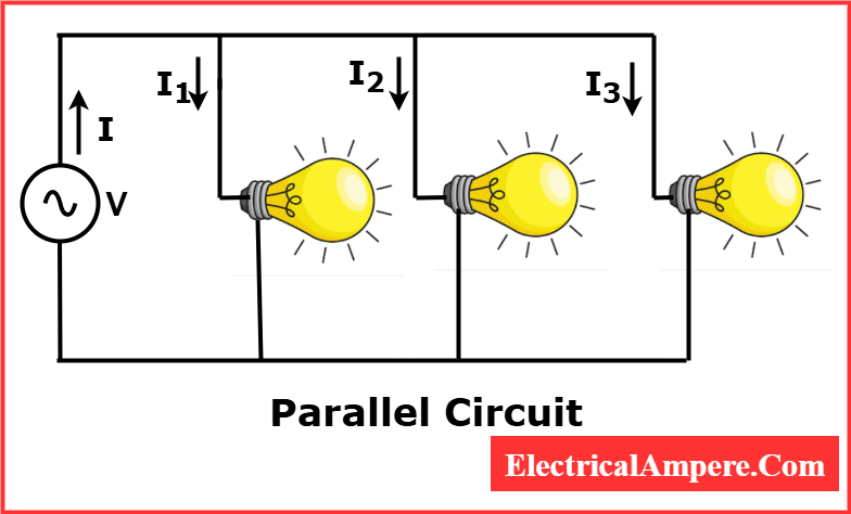
2. Parallel Electric Circuit – Features, Examples & Applications
In a parallel circuit, all components are connected across the same voltage source, creating multiple paths for current.
Key Features:
- Each component receives the full voltage of the source.
- The current divides among the different paths based on resistance.
- If one component fails, the others continue to work, making it more reliable than a series circuit.
Practical Examples:
- Household electrical wiring where lights, fans, and appliances operate independently.
- Street lighting systems, allowing some lights to remain on if one bulb fails.
Advantages:
- Provides consistent voltage to each component.
- Failure of one device does not affect others.
Disadvantages:
- Requires more wiring than series circuits.
- Can be more complex to design for large systems.
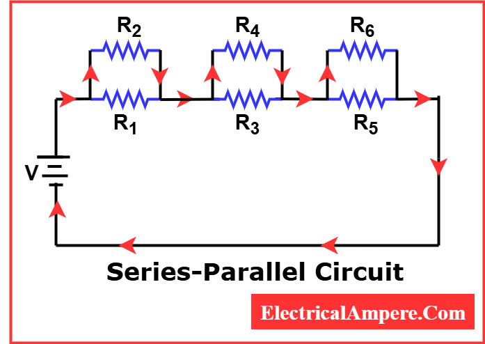
3. Series-Parallel Electric Circuit (Combination Circuit in Electrical Networks)
A series-parallel circuit, also called a combination circuit, includes both series and parallel connections in one network.
Key Features:
- Combines the advantages of series and parallel circuits.
- Allows some components to continue working even if part of the circuit fails.
- Balances current and voltage distribution more efficiently.
Practical Examples:
- Car electrical systems where multiple devices are powered but remain independent.
- Electronic devices like laptops and TVs that require both series and parallel connections for different parts.
Advantages:
- Flexible and reliable for complex electrical systems.
- Ensures efficient voltage and current management.
Disadvantages:
- More complicated to design and troubleshoot.
- Requires careful calculation of voltage drops and current flow.
Summary Table: Types of Electric Circuit for Quick Reference
| Circuit Type | Current | Voltage | Reliability | Example |
| Series | Same | Divides | Low | Christmas lights |
| Parallel | Divides | Same | High | Household wiring |
| Series-Parallel | Mixed | Mixed | Medium-High | Car electrical system |
Key Facts About Electrical Circuits and Networks
- When the switch is off, the circuit becomes open, stopping current flow.
- Circuits can be classified by current type: AC (alternating current) or DC (direct current).
- Electrical circuits are the foundation for designing control systems, power distribution, and electronics projects.
Understanding these facts is important for students, hobbyists, and professionals working in electrical networking.
Difference Between Electrical Circuits and Electrical Networks
An electrical circuit is a single closed loop through which current flows, while an electrical network consists of multiple interconnected circuits managing several paths and loads. Circuits are simple and easy to analyze, whereas networks are more complex and designed for larger systems.
The table below summarizes the key differences between electrical circuits and electrical networks:
| Feature | Electrical Circuit | Electrical Network |
| Definition | Single closed loop for current flow | Two or more interconnected circuits |
| Complexity | Simple | Complex |
| Current Flow | One path or basic series/parallel | Multiple paths with load distribution |
| Example | Flashlight, single lamp | Home wiring, industrial control panel |
| Analysis | Basic circuit rules | Network analysis methods |
Why Understanding Circuit Electricity is Important
Learning circuit electricity and electrical networks is essential not just for academics, but for practical, everyday applications:
- Safety: Knowledge of circuits helps prevent accidents such as electric shocks, short circuits, and fires.
- Troubleshooting: Understanding how circuits work allows you to identify and fix faults in home wiring, appliances, or industrial machinery.
- Design & Innovation: Fundamental for developing electronics, robotics, smart home devices, and IoT systems.
- Industrial Efficiency: Engineers use circuit principles to design control panels, motors, and automation systems that power industries safely and efficiently.
- Modern Smart Homes: Series-parallel circuits in smart devices, energy management systems, and IoT gadgets help optimize energy consumption and automate daily tasks.
By mastering circuits, learners and professionals gain skills that bridge theory and real-world problem solving.
Conclusion: Role of Electric Circuits in Electrical Networks
An electric circuit is the backbone of modern technology. From simple series circuits to complex electrical networks, knowing how electricity flows and how circuits operate is essential. Whether you are learning types of electric circuits, exploring electrical networking, or curious about circuit in electricity, mastering these concepts opens doors to practical applications in everyday life and advanced technology.
FAQs on Electric Circuits & Electrical Networking
There are three main types – Series, Parallel, and Series-Parallel (Combination) circuits.
The circuit becomes open, stopping current flow.
Yes, these are called series-parallel or combination circuits.
A circuit is a single path for current, while a network is multiple interconnected circuits.
Flashlights, home wiring, car electronics, computers, industrial machines.
Related Articles: