Definition: The Series Magnetic Circuit consists of various parts made of different magnetic materials and with varying sizes that carry the same magnetic field. Before understanding the series magnetic circuit, let’s understand the basics of a magnetic circuit and its reluctance.
What is a Magnetic Circuit?
A magnetic circuit refers to a path that magnetic flux follows within a material, typically a ferromagnetic substance like iron. It’s analogous to an electrical circuit, but instead of the flow of electric current, it involves the flow of magnetic flux. Components such as iron cores and coils are often part of a magnetic circuit. Understanding magnetic circuits is crucial in various applications, including transformers, motors, and generators.
What is a Magnetic Reluctance?
Magnetic reluctance refers to the measure of opposition a material offers to establish magnetic flux. It’s similar to electrical resistance in an electrical circuit but in the context of magnetism. Materials with high reluctance impede the flow of magnetic flux more strongly, while those with low reluctance allow flux to flow more easily. Reluctance depends on factors such as the material’s composition, shape, and size, and it’s an essential concept in understanding and designing magnetic circuits.
Series Magnetic Circuit Explanation
Consider a composite magnetic circuit consisting of three distinct magnetic materials, each with varying permeabilities and lengths and an air gap characterized by a permeability (μr) of 1. Each segment within the circuit possesses its reluctance. Refer to the diagram below for the illustration of the series magnetic circuit.
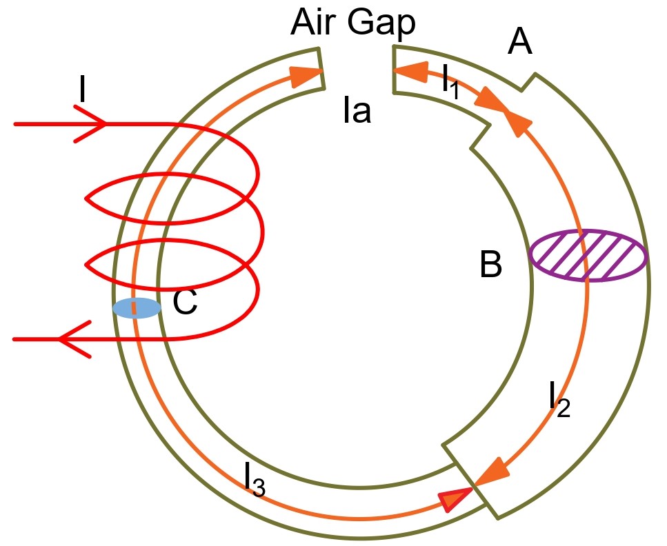
An electric current I flows through a solenoid with N turns wound around one section of a circular coil. Φ represents the flux created within the core of the coil.
In a part of the magnetic circuit, there’s a circular coil with N turns. When an electric current I flows through the solenoid, it induces a flux Φ within the core of the magnetic material.
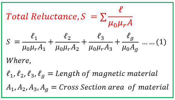
The overall reluctance of the circuit equals the sum of the reluctances along each path, given that they are connected in series.
The flux in the circuit is,
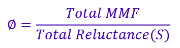
Therefore,
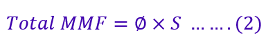
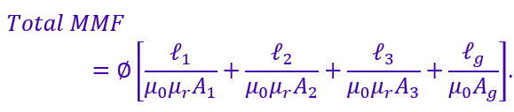
The value of total MMF by putting the value of reluctance in the above equation, we get;
We know φ=BA, therefore,
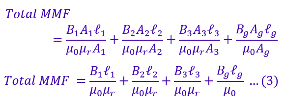
The magnetic flux density(B) is;
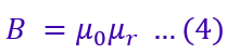
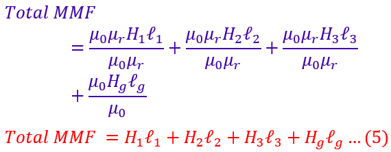
Putting the value of flux density from equation 4 in equation 3,
Procedure for the Calculation of the total MMF of a Series Magnetic Circuit
Following the steps below, we can calculate the total MMF in a series of magnetic circuits.
- List all the magnetic components in the series circuit, including the transformer core, coils, or any other magnetic devices.
- Determine the flux density(B) of all the sections using formula B = φ/a where φ is the magnetic flux in Weber, and a is the area of the cross-section in m2
- Calculates the magnetizing force (H) using the formula H = B/µ0µr, where B is the flux density in Weber/m2. The value of absolute permeability µ0 is 4πx10-7. The µr is the relative permeability of the material, and we know this value; we can calculate H. If the value of µr is unknown, you can determine it from the B-H curve of the magnetic material.
- You can determine the magnetizing force(H) by multiplying each section’s magnetizing force, H1, H2, H3, and Hg, with their respective section’s length, l1, l2, l3, and lg.
- The total MMF of a series magnetic circuit is;

Solved Example:
A series magnetic circuit consists of two magnetic materials: a ferromagnetic core with a reluctance of 6000 A/Wb and a magnetic material with a reluctance of 4000 A/Wb. The mean length of the toroidal is 0.4 meters. A coil with 10000 turns and a current of 4 A flowing through it is connected in series with these materials. Calculate the total magnetic flux in the circuit and the magnetic field intensity.
Given:
- Reluctance of the ferromagnetic core, Rcore=6000 A/Wb
- The reluctance of the additional magnetic material, Radditional=4000A/Wb
- Number of turns in the coil, N=1000
- Current flowing through the coil, I=4A.
- Length of toroidal, l= 0.4 m
Solution: To solve this problem, we’ll first find the equivalent reluctance of the series magnetic circuit and then use it to calculate the total magnetic flux and field intensity.
- Total Reluctance (Rtotal) in series:
Rtotal=Rcore+Radditional - Magnetic Flux (Φ) using the total reluctance:Φ=NI/Rtotal
- Magnetic Field Intensity (H) using the mean length of the coreeH=NI/lcore
Steps:
- Calculate the total reluctance (Rtotal).
- Calculate magnetic flux (Φ).
- Calculate the magnetic field intensity (H).
Solution:
- Total Reluctance (Rtotal):
=Rcore+Radditional
=6000+4000
=10000A/Wb - Magnetic Flux (Φ):
=NI/Rtotal
=(1000×4)/10000
=0.4 Weber - Magnetic Field Intensity (H):
=NI/lcore
=(1000 X4)/0.4
= 10000 A/m
Conclusion:
In conclusion, a series magnetic circuit comprises various magnetic elements interconnected sequentially, such as cores, coils, and other devices. The sum of the reluctance along each path determines the total reluctance of the circuit. Understanding the behavior of a series of magnetic circuits is essential in designing and analyzing magnetic systems and facilitating applications in transformers, motors, generators, and various other electromagnetic devices. In this article, you have learned,
- The same magnetic flux Φ flows through the circuit in a series magnetic circuit.
- Total reluctance is the sum of individual reluctance.
- The total MMF required for producing the flux is the sum of the MMFs for the various sections.
Related Articles: