Definition: The magnetic circuit is the closed path taken by magnetic lines of force that start and end at the same point. Magnetic flux can be generated by either permanent magnets or electromagnets.
A magnetic circuit consists of magnetic materials with high permeability, such as iron and soft steel. They are used in various devices, including electric motors, transformers, relays, generators, and galvanometers.
When a current of I ampere passes through a solenoid having N turns wound on an iron core, it generates a magnetic flux of ø Weber in the core. The magnetic circuit is shown in the image below.
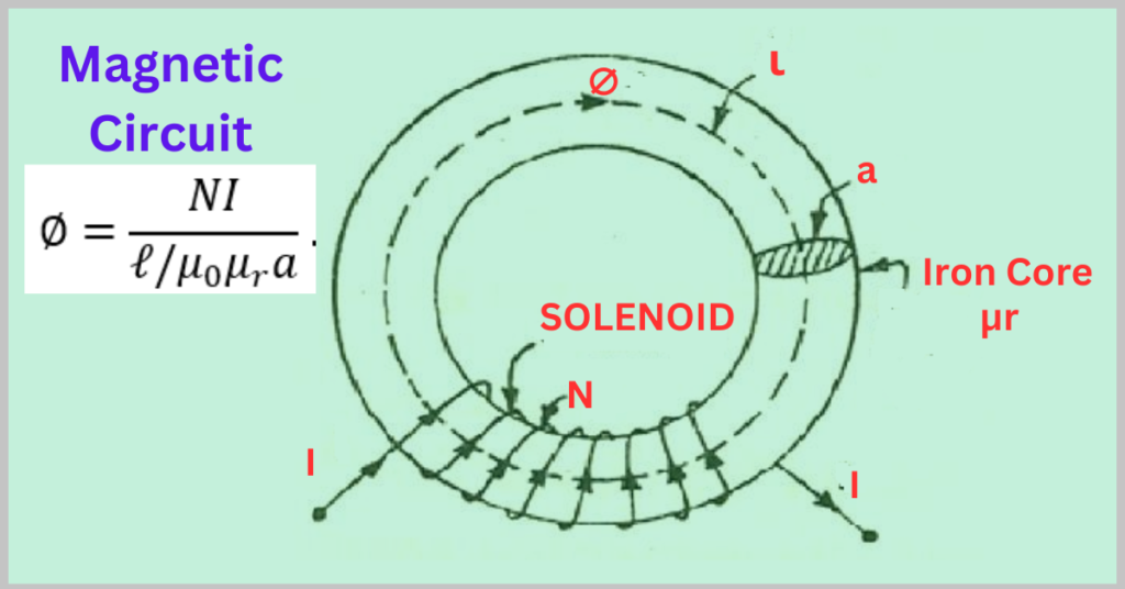
Let
l = mean length of the magnetic circuit
A = cross-sectional area of the core
µr = relative permeability of the core
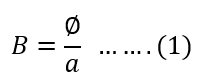
The flux density in the core material is,
As per the law of work, the work carried out in rotating a single magnetic pole unit around the magnetic circuit is equivalent to the number of ampere-turns enclosed by the same circuit.
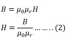
The field strength (H) is,
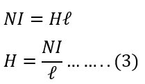
The magnetomotive force(NI) is,
Putting the value of field strength (H) and flux density (B) from equation 3 and 1 in equation 2,
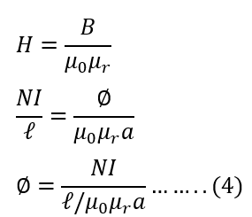
The equation provided explains the following concepts.
- The magnetic flux is directly proportional to the number of turns (N) and the current (I). It shows that the flux increases if the number of turns or current increases and decreases when the two quantities decrease.
NI represents the magnetomotive force (MMF). - The magnetic flux is inversely proportional to the reluctance, where l/a µ0µr is the reluctance. The amount of flux is inversely proportional to the reluctance. This means that if the reluctance is low, the flux will be high, and if the reluctance is high, the flux will be low.
Related Articles: