An Electrical Resonance Type Frequency Meter is an electrical measuring instrument used to determine the frequency of an alternating current (AC) supply. It operates on the principle of electrical resonance, in which the inductive and capacitive reactances of a circuit become equal at a particular frequency.
This type of frequency meter uses an inductive coil, a capacitor and a moving-coil arrangement to indicate the supply frequency. It is commonly designed for measuring frequencies around the standard power-system frequency. For example, some instruments have a measurement range of approximately 45 Hz to 55 Hz.
Electrical resonance type frequency meters are useful in electrical power systems, generating stations and substations where monitoring supply frequency is important for maintaining stable operation.
Principle of Electrical Resonance Type Frequency Meter
The working principle of an electrical resonance type frequency meter is based on the phenomenon of electrical resonance in an LC circuit.
An LC circuit consists of an inductor (L) and a capacitor (C). The inductive reactance increases with frequency, whereas the capacitive reactance decreases as frequency increases.
At the resonant frequency, both reactances become equal in magnitude:
The resonant frequency is calculated using:
Where:
- = Resonant frequency in Hz
- = Inductance in henry
- = Capacitance in farad
At resonance, the circuit produces a characteristic electrical response. The instrument uses this frequency-dependent response to operate its indicating mechanism and display the measured frequency.
Construction of Electrical Resonance Type Frequency Meter
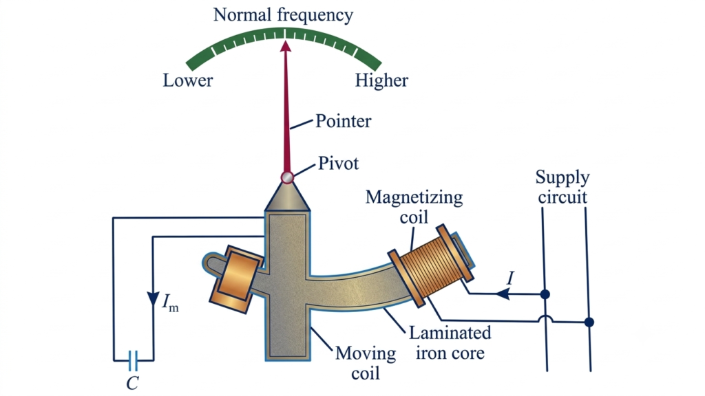
An electrical resonance type frequency meter consists of a fixed coil, a specially shaped iron core, a moving coil, a capacitor and a pointer arrangement.
The main components are explained below.
1. Fixed Coil or Magnetizing Coil
The fixed coil is also known as the magnetizing coil. It is connected to the AC supply whose frequency is to be measured.
The coil is mounted on a laminated iron core and produces a magnetic field when current flows through it. This magnetic field provides the excitation required for the operation of the instrument.
2. Laminated Iron Core
The iron core provides a magnetic path for the flux produced by the fixed coil.
Its cross-sectional area gradually changes along its length. The section is generally larger near the end where the magnetizing coil is installed and becomes smaller towards the other end.
This specially shaped core helps establish the magnetic field required for the moving-coil arrangement.
3. Moving Coil
The moving coil is mounted on the iron core and is free to rotate. A pointer is attached to this coil to indicate the measured frequency on a calibrated scale.
The moving coil interacts with the magnetic flux produced by the fixed coil. Its position changes according to the electromagnetic forces acting on it.
4. Capacitor
A capacitor is connected with the moving-coil circuit. It provides capacitive reactance, which varies with the supply frequency.
Together with the inductive elements, the capacitor forms the frequency-dependent resonant arrangement used in the instrument.
5. Pointer and Calibrated Scale
The pointer is mechanically connected to the moving coil and moves over a calibrated frequency scale.
The scale is marked in Hertz (Hz), allowing the operator to read the frequency directly.
6. Absence of Conventional Controlling Force
Unlike many conventional analog measuring instruments, the arrangement described in this frequency meter does not use a conventional controlling spring or suspended weight.
The pointer position is determined by the electromagnetic interaction between the fixed-coil magnetic field and the moving-coil system.
Working of Electrical Resonance Type Frequency Meter
The operation of an electrical resonance type frequency meter depends on the frequency-related changes in inductive and capacitive reactance.
When the AC supply is connected to the magnetizing coil, it produces magnetic flux in the laminated iron core. The moving coil and its associated capacitor respond to this magnetic field and the applied frequency.
The operation can be understood through the following steps:
Step 1: Application of AC Supply
The unknown AC supply is connected to the fixed magnetizing coil. Current flowing through this coil produces an alternating magnetic field in the iron core.
Step 2: Magnetic Flux Generation
The magnetic flux produced by the fixed coil passes through the iron core and links with the moving-coil arrangement.
The magnitude and phase relationship of the flux depend on the electrical conditions of the circuit.
Step 3: Induced EMF in the Moving Coil
The changing magnetic flux linking the moving coil induces an electromotive force (EMF) in it according to Faraday’s law of electromagnetic induction.
The induced EMF has a phase relationship with the flux that depends on the direction of the winding and the reference convention used.
Step 4: Effect of Inductive and Capacitive Reactance
The moving-coil circuit contains inductive and capacitive elements. Their reactances vary with the applied frequency.
Inductive reactance is given by:
Capacitive reactance is given by:
As the supply frequency changes, the relative effects of these reactances also change. This influences the current and electromagnetic torque acting on the moving coil.
Step 5: Pointer Movement
The electromagnetic interaction between the fixed-coil flux and moving-coil system produces the torque responsible for pointer movement.
The pointer settles at a position determined by the operating conditions of the instrument. Its calibrated scale indicates the corresponding supply frequency.
Thus, the frequency is determined by observing the pointer position rather than directly counting electrical cycles.
Advantages of Electrical Resonance Type Frequency Meter
The main advantages of an electrical resonance type frequency meter include:
- Simple operation: It provides a direct indication of supply frequency through a calibrated pointer.
- Reliable measurement: It can provide dependable readings when operated within its specified frequency range.
- No separate external power requirement: Some designs operate directly from the measured AC supply.
- Good measurement accuracy: Properly designed and calibrated instruments can provide satisfactory accuracy for their intended applications.
- Economical construction: Its electromechanical arrangement can be relatively simple and cost-effective.
Disadvantages of Electrical Resonance Type Frequency Meter
Despite its advantages, an electrical resonance type frequency meter has some limitations.
- Limited frequency range: Instruments designed for power-system applications generally operate over a narrow frequency range.
- Temperature effects: Changes in temperature can affect the inductance, capacitance and other circuit characteristics, influencing measurement accuracy.
- Magnetic field interference: External magnetic fields may affect the electromagnetic measuring mechanism.
- Calibration requirements: Proper calibration is necessary to maintain reliable frequency readings.
- Not suitable for all high-frequency applications: A power-frequency resonance meter cannot be used outside its specified operating range without an appropriate redesign.
Applications of Electrical Resonance Type Frequency Meter
Electrical resonance type frequency meters are used in applications where AC supply frequency needs to be monitored.
1. Generating Stations
These instruments can be used to monitor generator output frequency and help operators observe variations in the generated electrical supply.
2. Electrical Substations
They can be installed in electrical panels and substations to provide an indication of the incoming AC supply frequency.
3. Power System Monitoring
Frequency monitoring helps engineers identify deviations from the normal operating frequency and assess the operating condition of an electrical power system.
4. Industrial Electrical Systems
Industrial installations use frequency measurement to monitor the AC supply provided to motors, transformers and other electrical equipment.
5. Educational Laboratories
Electrical resonance type frequency meters can be used in engineering laboratories to demonstrate electrical resonance, inductive reactance, capacitive reactance and frequency measurement principles.
6. Electrical Testing and Instrumentation
These instruments can be used in testing arrangements where frequency indication within their specified operating range is required.
Conclusion
An electrical resonance type frequency meter is an electromechanical instrument that measures AC frequency using the principle of electrical resonance. Its construction includes a fixed magnetizing coil, a laminated iron core, a moving coil, a capacitor and a pointer mechanism.
Changes in supply frequency affect the inductive and capacitive reactances of the circuit, influencing the electromagnetic torque and pointer position. The calibrated scale then indicates the corresponding frequency.
Although modern digital frequency meters offer greater flexibility and wider measurement capabilities, electrical resonance type frequency meters remain useful for understanding resonance-based frequency measurement and monitoring AC supplies within their designed operating range.
Read Next:
- Analog Instruments: Definition, Classification, and Working Principle
- Null Type Instrument: Principle, Example, and Key Advantages
- Types of Measuring Instruments in Electrical Engineering
- Integrating Instruments: Classifications, Advantage and Applications
- Digital Instruments: Definition, Characteristics, Construction, Advantages, and Disadvantages
- Analog Frequency Meter: Working, Types and Applications
- Digital Frequency Meter: Working Principle, Block Diagram, Construction
- Vibrating Reed Frequency Meter: Principle, Construction, Working