A single phase energy meter connection diagram shows how an energy meter is connected between the incoming AC supply and the electrical load to measure energy consumption in kilowatt-hours (kWh). In a typical single-phase, two-wire system, the meter is connected to the phase and neutral conductors according to the manufacturer’s terminal diagram.
Single-phase energy meters are widely used in houses, shops, offices, and small commercial installations. Understanding their terminal connections helps electricians and electrical engineering students understand how the supply reaches the load and how energy consumption is recorded.
This article explains the single phase energy meter wiring diagram, terminal identification, connection procedure, working principle, and essential safety precautions.
Single Phase Energy Meter Connection Diagram
The following diagram illustrates a typical single-phase, two-wire energy meter connection using a four-terminal direct-connected meter. The terminal arrangement is illustrative; always verify the actual terminal markings on the meter before installation.
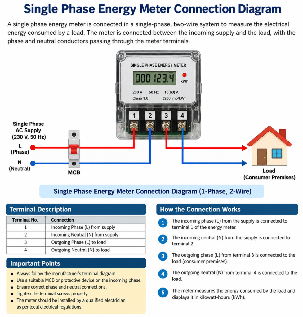
1. Terminal Connections of a Single Phase Energy Meter
A common four-terminal single phase energy meter uses two terminals for the incoming supply and two for the outgoing load connection.
| Terminal | Typical connection | Function |
|---|---|---|
| 1 | Incoming phase (L) | Receives phase supply |
| 2 | Incoming neutral (N) | Receives neutral supply |
| 3 | Outgoing phase (L) | Supplies phase to the load |
| 4 | Outgoing neutral (N) | Supplies neutral to the load |
Important: This terminal numbering is common in some direct-connected meters, but it is not universal. Some meters use different terminal arrangements or additional terminals. Always follow the wiring diagram printed on the meter or supplied by its manufacturer.
2. How to Connect a Single Phase Energy Meter
The connection follows the general sequence below for a compatible four-terminal meter.
- Incoming phase: The phase conductor from the supply passes through the required protective device and connects to the designated phase-input terminal.
- Incoming neutral: The neutral conductor connects to the designated neutral-input terminal.
- Outgoing phase: The phase-output terminal connects to the consumer’s distribution board or load circuit.
- Outgoing neutral: The neutral-output terminal connects to the corresponding neutral connection for the load.
- Protective earthing: The protective earth conductor is connected to the installation’s earthing system as required. It is not substituted for the neutral conductor or routed through the energy meter’s current-measuring path.
The meter measures the energy consumed by the connected load and accumulates the reading in kWh.
Meter installation must be carried out by a qualified electrician or authorized utility personnel, with the supply isolated and verified safe before connections are handled.
3. Working Principle of the Connection
When the supply is energized and the load operates, current flows through the meter’s designated current path. The meter also senses the supply voltage.
An electronic energy meter calculates active power from voltage and current measurements and integrates the power over time to determine energy consumption.
The energy relationship is:
Where:
- = electrical energy in kWh
- = active power in kW
- = operating time in hours
For example, if a 1.5 kW load operates for 4 hours, the energy consumed is:
Therefore, the meter records approximately 6 units of electricity, assuming constant power and no other loads.
Difference Between Single Phase and Three Phase Meter Connections
| Parameter | Single Phase Meter | Three Phase Meter |
| Supply | Single-phase AC | Three-phase AC |
| Common application | Homes and small shops | Commercial and industrial installations |
| Measurement | Single-phase energy consumption | Three-phase energy consumption |
| Wiring | Commonly phase and neutral | Three-phase, with or without neutral depending on the system |
| Meter terminals | Depends on meter design | Depends on direct or CT-operated configuration |
Common Wiring Mistakes to Avoid
Incorrect connections can cause measurement errors, equipment damage, or electric shock.
- Connecting conductors without checking the manufacturer’s terminal diagram.
- Reversing incoming and outgoing connections where the meter design requires a specific direction.
- Leaving terminals loose or using conductors of an unsuitable size.
- Bypassing required protective devices.
- Confusing neutral with protective earth.
- Opening a sealed utility meter or modifying its connections without authorization.
If the meter shows no reading, unexpected consumption, or an error indication, have the installation and meter checked by authorized personnel.
Conclusion
A single phase energy meter connection diagram helps explain how the phase and neutral conductors connect the incoming supply to the consumer’s load through the meter. In a common four-terminal design, the meter receives the supply through its input terminals and delivers it to the load through its output terminals.
Correct terminal identification, suitable protection, secure connections, and compliance with the manufacturer’s instructions are essential for accurate energy measurement and safe operation.
Read Next: