Electrical transmission losses—including resistive, capacitive, and inductive losses—have a substantial impact on the overall efficiency of power transmission lines. These losses in transmission lines contribute significantly to electricity transmission loss and, in turn, to our carbon footprint. Reducing power transmission losses within the electric power transmission system can lead to improved sustainability and energy savings.
Understanding the origin of these transmission line losses is the first crucial step toward minimizing them. Let’s explore the different types of losses in transmission lines and how they affect power in transmission lines.
What Causes Electrical Transmission Losses in Power Lines?
Electrical transmission losses primarily occur because most materials used in power lines are not perfect conductors. As electricity travels through transmission power lines, a portion of it is inevitably lost due to resistance. This loss is commonly referred to as power transmission loss or electricity transmission loss.
One of the fundamental reasons for transmission line losses is the heat generated when current flows through conductors. According to the power formula:
Power = Voltage × Current
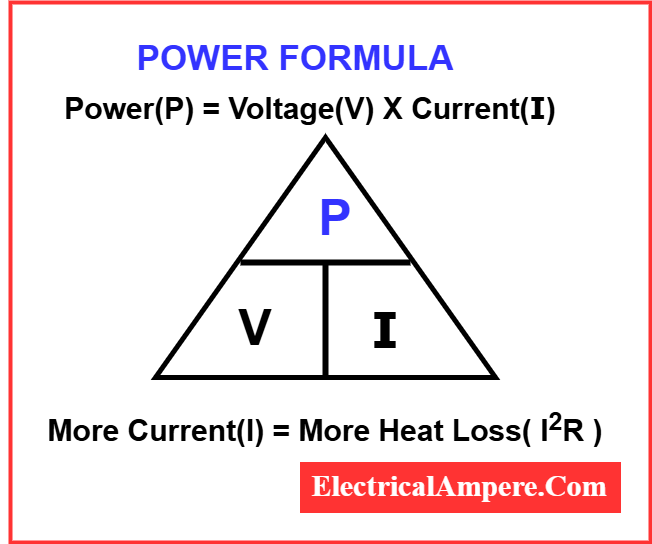
For a fixed amount of power, increasing the voltage reduces the current. This is crucial because higher current results in more heat, leading to greater power losses. Therefore, in electrical power transmission systems, power is transmitted at high voltages. This minimizes transmission losses by keeping current low, which in turn reduces heat generation along transmission lines.
To put it simply, transmission line loss is directly related to the amount of current flowing through the lines. Higher voltages mean lower current, and lower current means reduced losses in transmission lines.
Another factor contributing to power loss is the physical size or gauge of the conductor. Cables carrying high transmission voltages can be thinner because of the lower current. In contrast, lines operating at lower voltages need thicker conductors (heavier gauge wires) to handle the increased current without overheating—similar to how a pipe must be wider to carry more water when pressure is low.
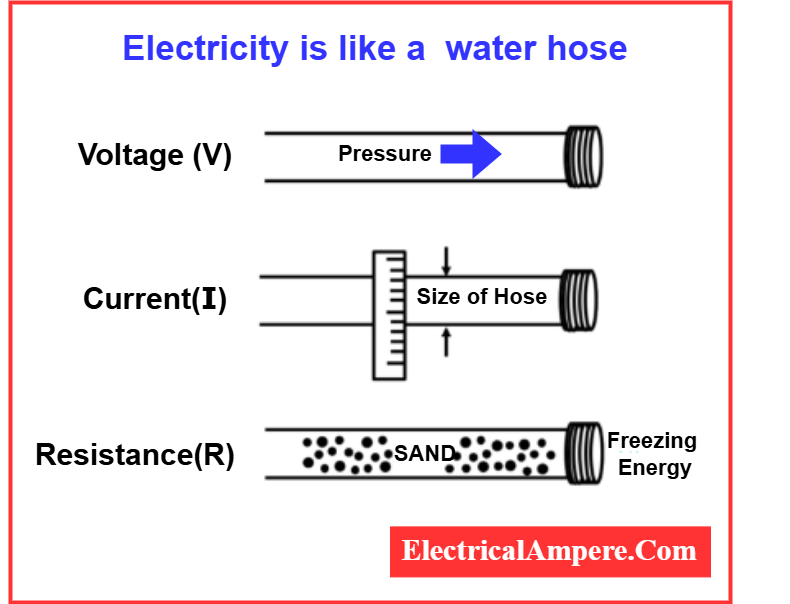
This analogy helps explain why electric power transmission lines are designed with both voltage level and conductor size in mind, optimizing for efficiency and minimal electricity transmission losses across long distances in the electrical transmission system.
Three Primary Types of Electrical Transmission Losses
Electrical transmission losses occur not only in high-voltage transmission systems but also in low and medium-voltage networks. The three primary types of transmission line losses are resistive, capacitive, and inductive losses. These power losses largely stem from heat generated when electric current faces impedance as it travels through transmission power lines.
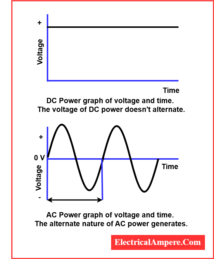
Both high and low voltage electric power transmission systems suffer from these types of losses. In AC transmission, all three types—resistive, capacitive, and inductive—are present. In contrast, DC power transmission experiences only resistive losses and is unaffected by capacitive or inductive losses. For example, resistive transmission losses like the skin effect (where current flows mostly on the surface of a conductor) impact AC systems but not DC systems.
Surprised? You’re not alone. A widespread misconception is that DC electricity transmission losses are higher than AC. If DC incurs fewer line losses, then why does the modern electrical power transmission system predominantly use high-voltage AC? The answer lies in history and practicality.
AC became the standard during the late 19th-century “War of Currents” because it’s compatible with transformers, which efficiently step voltages up or down. This makes AC easier and cheaper to transmit over long distances using power transmission line voltage levels of 110kV or more. Consequently, electricity transmission losses in high-voltage AC systems are considered manageable due to this economic benefit.
However, the association of DC with low-voltage systems—like those in electric distribution lines—leads to confusion. Since power loss increases with current (and current increases as voltage drops), low-voltage DC systems naturally suffer more power loss. This has led many to falsely assume that DC is inherently less efficient. In reality, at equal voltage levels, DC suffers fewer electric power transmission losses compared to AC. That’s because AC is prone to capacitive and inductive transmission line losses, while DC is not.
To truly understand the distinction, let’s explore resistive losses in more detail—specifically why both AC and DC systems are affected by them, and how they differ from other types of losses in transmission lines.
Resistive Line Losses in Electrical Transmission Systems
Resistive power losses are one of the most common types of electrical transmission losses in power systems. These losses occur when electrical energy is converted into heat as it flows through conductors, such as transmission power lines. Since no conductor is perfectly efficient (except superconductors), all standard power lines have some level of electrical resistance. This resistance causes part of the electric power to be lost as heat, especially over long distances.
image source: thegeekpub.com
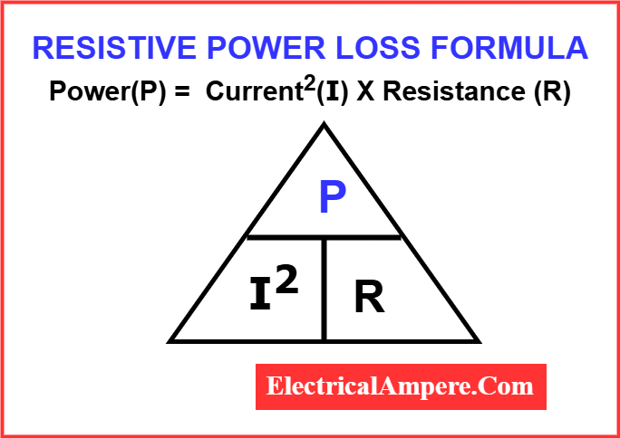
Here is the formula to calculate resistive power loss in electrical transmission lines:
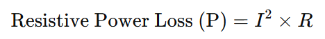
Where:
- P = Power loss (in watts)
- I = Current flowing through the conductor (in amperes)
- R = Resistance of the conductor (in ohms)
This formula highlights why electrical transmission losses are higher when current is increased—since power loss is proportional to the square of the current. That’s why power transmission systems often use high voltages: to reduce current and minimize power losses in transmission lines.
This heat generation leads to a voltage drop along the line, which reduces the efficiency of the electric power transmission system. These losses in transmission lines are also called conductor losses, as they primarily result from the inherent resistance of the conductor material itself.
Resistive transmission line losses affect both AC and DC systems, making them a universal concern in any type of electrical transmission line voltage setup. However, AC transmission also experiences additional losses like inductive and capacitive losses, while DC transmission lines only suffer from resistive losses.
There are also subtypes of resistive power losses worth noting. These include:
- Skin Effect – where AC current tends to flow near the surface of the conductor, increasing resistance.
- Dielectric Loss – related to the insulating materials around conductors that also dissipate energy as heat under alternating electric fields.
Understanding and minimizing resistive losses is crucial for improving the overall efficiency of power in transmission lines, especially in high-voltage, long-distance systems. Engineers must consider power loss formulas when designing electrical transmission systems to keep power transmission losses as low as possible.
Capacitive Line Losses in Electrical Transmission Systems
Capacitive line losses are a specific type of electric power transmission losses that occur only in alternating current (AC) systems. These losses are categorized as reactive power losses, meaning they don’t directly do useful work but still contribute to power transmission loss in the system—primarily in the form of heat. Unlike resistive losses, capacitive losses do not appear in direct current (DC) circuits.
What is Capacitance in Power Transmission Lines?
In the context of electrical transmission lines, capacitance is the ability of two conductors to store energy in an electric field when placed near each other. Whenever two conductors, such as power transmission lines and the Earth, run parallel and are close enough, a phenomenon called parasitic capacitance occurs. This is an unwanted effect—hence the term “parasitic.”
Essentially, every electric power transmission line has a natural capacitive relationship with the ground. When alternating voltage is applied to these lines, it creates an oscillating electric field. As a result, energy is momentarily stored and released between the power line and the Earth. This repeated charging and discharging lead to capacitive line losses—a form of electricity transmission losses that can be significant in high power voltage lines.
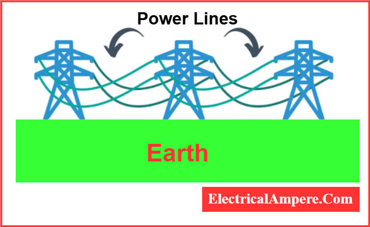
Ever wondered why transmission power lines are strung so high above the ground? One major reason is to reduce capacitance-related losses. The higher the power lines are placed, the weaker the interaction between their electric fields and the Earth’s surface. This helps minimize transmission line losses and improves the efficiency of the electrical power transmission system.
AC vs. DC: Capacitive Losses
Capacitive line losses do not occur in DC transmission systems because DC provides a constant voltage with no frequency. Without the alternating electric field found in AC systems, there’s no mechanism for capacitance to build between the electric distribution lines and Earth. This makes DC power transmission more efficient in certain long-distance scenarios where transmission losses must be minimized.
Inductive Line Losses in Electrical Transmission Systems
Inductive line losses represent the third major type of electrical transmission losses, and they primarily affect AC power transmission systems. These power losses occur due to the repeated formation and collapse of magnetic fields around the transmission lines, a phenomenon that is unique to alternating current (AC) systems.
What Causes Inductive Power Losses?
Every electrical power transmission line carrying AC behaves like a long, distributed inductor. When current flows through a wire, it generates a magnetic field. In AC systems, the direction of current constantly alternates, which causes the magnetic field to repeatedly build up and collapse. These fields store energy temporarily, and while doing so, some of this energy is lost as heat. The energy that doesn’t reach the end user but instead gets trapped and released as heat in these magnetic fields contributes to inductive power transmission losses.
These transmission line losses are a form of reactive power loss—just like capacitive losses—and they do not directly contribute to the usable power delivered to homes, industries, or equipment. Instead, they circulate within the electric power transmission system, contributing to overall power transmission loss.
Inductive Losses in AC vs. DC Systems
Inductive line losses are absent in DC transmission lines. This is because direct current (DC) has a constant, non-alternating flow of electricity. With no change in current direction, no fluctuating magnetic field is produced, meaning the parasitic inductance of the wire doesn’t get activated. As a result, electricity transmission losses from inductance do not occur in DC circuits—making DC more efficient in some high power voltage line applications.
This difference plays a crucial role in modern electrical transmission systems, especially when comparing the efficiency of AC vs. DC power for long-distance transmission. While AC power is still dominant due to ease of voltage transformation via transformers, DC transmission is increasingly used in ultra-high voltage scenarios where reducing power losses is critical.
Conclusion: The Future of Power Transmission Lies in DC
When evaluating power losses in generation, transmission, and distribution, it’s easy to get overwhelmed by the many types of line losses—resistive, capacitive, and inductive—and their various subtypes. However, most transmission line losses stem from the alternating frequency of AC power and the heat that results from it.
Historically, AC power was chosen over DC power more than a century ago due to its compatibility with transformers, which made it easy to step voltages up or down for long-distance transmission. At the time, most electrical loads—like incandescent bulbs—were well-suited to AC electricity, making it the logical choice.
But today’s energy landscape has shifted dramatically.
First, electricity now travels much greater distances than before. As a result, more transmission projects span over 600 km, the break-even point where HVDC (High Voltage Direct Current) becomes more economical and efficient than AC. In international power sharing, frequency mismatches between countries (50 Hz vs. 60 Hz) add complexity to AC transmission. In such cases, converting AC to DC for long-distance travel and then back to AC at the receiving country’s frequency provides a more streamlined solution. These DC interconnections, known as asynchronous grids, eliminate the need for frequency synchronization—reducing infrastructure costs and simplifying cross-border power flow.
Second, as we move toward greener energy sources, DC power is taking center stage. Technologies like solar panels and wind turbines naturally generate DC power. Pairing these with DC transmission avoids unnecessary conversions, improving overall efficiency and reducing losses.
Lastly, consumer demand is driving this shift. More of our modern devices—from electric vehicles (EVs) to HVAC systems with DC motors—operate on DC electricity. In homes with EVs and smart appliances, DC loads now account for over 74% of total electrical consumption—and that share continues to grow.
In summary, HVDC transmission isn’t just an energy-efficient alternative to traditional AC lines—it’s a vital component of a modern, clean, and resilient power grid. It supports cross-border energy sharing, integrates more smoothly with renewable energy sources, and better aligns with the digital and electrified world we’re rapidly building.
Read Next: