A voltmeter multiplier is a high-value resistance connected in series with a voltmeter’s measuring mechanism to extend its voltage measurement range. It is commonly used with a Permanent Magnet Moving Coil (PMMC) instrument to measure voltages higher than the rated voltage of its moving coil.
The multiplier resistance limits the current flowing through the moving coil and protects it from excessive current. It also helps maintain a high input resistance, minimizing the effect of the voltmeter on the circuit being measured.
In this article, you will learn about the working principle, construction, material, formula, and calculation of a voltmeter multiplier with a solved numerical example.
What Is a Voltmeter Multiplier?
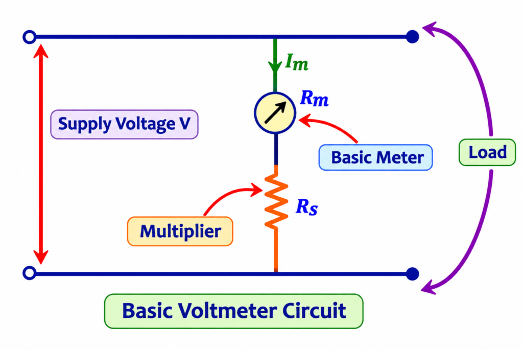
A voltmeter multiplier is a high resistance connected in series with the moving coil of a PMMC instrument to convert it into a voltmeter with a higher voltage range.
A PMMC instrument has a low internal resistance and is designed to carry only a small current at full-scale deflection. Therefore, connecting it directly across a high-voltage source can damage its moving coil.
To overcome this limitation, a suitable series resistance is connected with the moving coil. This resistance is called a voltmeter multiplier.
The multiplier drops most of the applied voltage, allowing only the rated full-scale deflection current to flow through the moving coil.
For example: If a PMMC movement is designed for 1 V but needs to measure up to 100 V, a suitable series resistance is connected to extend its measuring range to 100 V.
Functions of a Voltmeter Multiplier
A voltmeter multiplier performs the following important functions:
1. Limits current: It restricts the current through the moving coil to its rated full-scale deflection value, protecting the instrument from excessive current.
2. Extends voltage range: It allows a low-voltage PMMC movement to measure higher voltages by adding an appropriate series resistance.
3. Increases input resistance: It increases the overall resistance of the voltmeter, reducing the current drawn from the circuit under measurement.
4. Improves measurement accuracy: A sufficiently high input resistance minimizes the loading effect, thereby reducing errors caused by the voltmeter itself.
Working Principle of Voltmeter Multiplier
The working principle of a voltmeter multiplier is based on Ohm’s law.
When a series resistance is connected with the PMMC moving coil, the applied voltage is divided between the coil resistance and the multiplier resistance.
Since both resistances are connected in series, the same current flows through them.
According to Ohm’s law:
Where:
- = Total voltage applied to the voltmeter
- = Current flowing through the circuit
- = Internal resistance of the moving coil
- = Multiplier resistance
At full-scale deflection, the current reaches its rated value. The multiplier resistance drops the excess voltage, while the moving coil receives only the voltage it is designed to withstand.
Thus, a PMMC movement can measure a voltage much higher than its original range without exceeding its rated current.
Voltmeter Multiplier Circuit Diagram
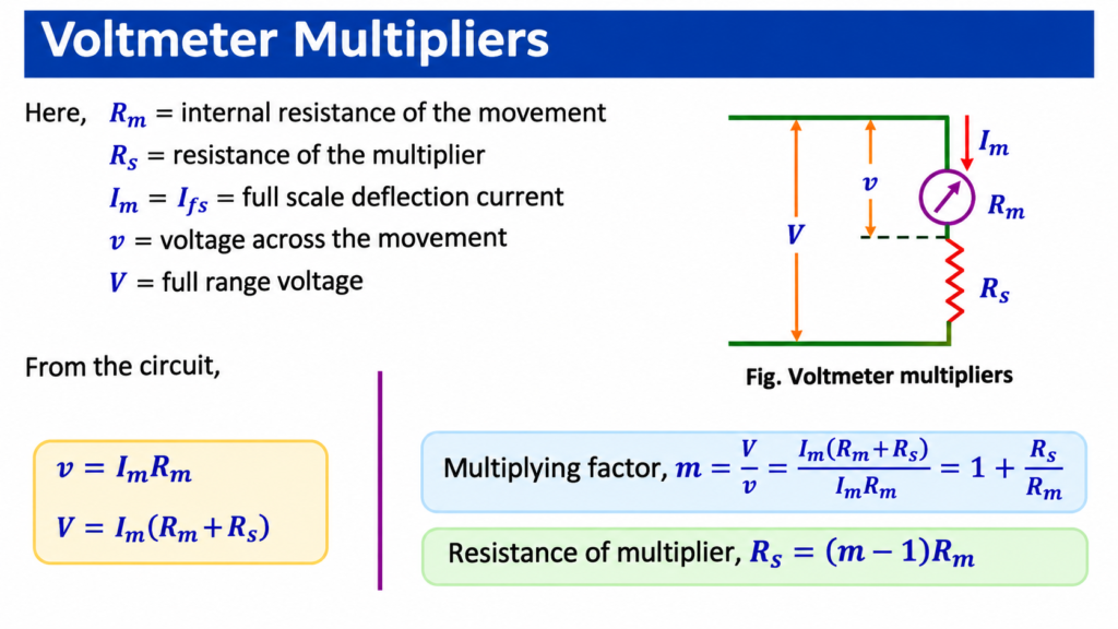
The circuit consists of two main resistances:
- Meter resistance : The internal resistance of the PMMC moving coil.
- Multiplier resistance : An external high resistance connected in series with the moving coil.
The total resistance of the voltmeter is:
The multiplier resistance is selected according to the required voltage range and the full-scale deflection current of the instrument.
Voltmeter Multiplier Formula and Derivation
The value of the multiplier resistance depends on the meter’s internal resistance, full-scale deflection current, and desired voltage range.
Let:
- = Full-scale deflection current of the meter (A)
- = Internal resistance of the moving coil (Ω)
- = Multiplier resistance (Ω)
- = Voltage across the moving coil (V)
- = Maximum voltage range of the voltmeter (V)
- = Multiplying factor
According to Ohm’s law, the voltage across the moving coil is:
The total applied voltage across the voltmeter is:
Dividing equation (2) by equation (1):
Simplifying:
The multiplying factor is:
Therefore:
Rearranging the equation to calculate multiplier resistance:
Since:
The final formula becomes:
Alternatively, since :
These formulas are used to calculate the series resistance required to extend the voltage range of a PMMC instrument.
What Is the Multiplying Factor of a Voltmeter?
The multiplying factor is the ratio of the extended voltage range to the original voltage range of the PMMC movement.
It indicates how many times the original measuring range has been increased by connecting a multiplier resistance.
The formula is:
Where:
- = Multiplying factor
- = Extended voltage range
- = Original voltage range of the meter movement
Example:
Suppose a PMMC movement has a voltage rating of 0.25 V, and we want to extend its range to 10 V.
The multiplying factor is:
This means that the original voltage range has been increased by 40 times.
Numerical Example: Calculation of Voltmeter Multiplier Resistance
Problem: A PMMC instrument has an internal resistance of 25 Ω and requires 10 mA for full-scale deflection. Calculate the multiplier resistance required to convert it into a 10 V voltmeter.
Given data:
- Internal resistance,
- Full-scale deflection current,
- Desired voltage range,
Step 1: Calculate the voltage across the moving coil.
Using Ohm’s law:
Substituting the values:
Step 2: Calculate the multiplying factor.
Step 3: Calculate the multiplier resistance.
Using the formula:
Substituting the values:
The required voltmeter multiplier resistance is 975 Ω.
Therefore, connecting a 975 Ω resistance in series with the PMMC movement will extend its voltage range to 10 V.
Construction of Voltmeter Multiplier
A voltmeter multiplier is generally constructed using a high-resistance element connected in series with the measuring movement.
The resistance is selected to provide the required voltage drop while maintaining the rated current through the moving coil.
The important construction requirements are:
1. High resistance: The multiplier should have sufficient resistance to extend the voltage range and limit the current through the moving coil.
2. Low temperature coefficient: Its resistance should remain nearly constant when the surrounding temperature changes.
3. Long-term stability: The resistance value should not change significantly with time, ageing, or continuous operation.
4. Low inductance: The multiplier should have low inductance, particularly when used for AC voltage measurement, to minimize frequency-dependent measurement errors.
5. Proper insulation: The resistor and its connections should have adequate insulation to withstand the applied voltage safely.
Materials Used for Voltmeter Multiplier
The resistance material used in a voltmeter multiplier should have a low temperature coefficient of resistance and good long-term stability.
Commonly used materials include:
1. Manganin
Manganin is a copper-manganese-nickel alloy widely used for precision resistance applications.
Its important properties include:
- Very low temperature coefficient of resistance.
- Good resistance stability over time.
- Relatively high resistivity.
- Low thermoelectric EMF against copper.
Its nominal composition is approximately:
| Element | Composition |
| Copper (Cu) | 84% |
| Manganese (Mn) | 12% |
| Nickel (Ni) | 4% |
2. Constantan
Constantan is an alloy primarily consisting of copper and nickel. It has relatively high resistivity and a low temperature coefficient of resistance.
It is also used in resistance applications where stable electrical characteristics are required.
Advantages of Voltmeter Multiplier
The major advantages of using a multiplier resistance in a voltmeter are:
- It extends the voltage measurement range of a PMMC instrument.
- It protects the moving coil from excessive current.
- It increases the input resistance of the voltmeter.
- It reduces the loading effect on the measured circuit.
- It provides a simple and economical method of converting a galvanometer or PMMC movement into a voltmeter.
Applications of Voltmeter Multiplier
Voltmeter multipliers are used in several electrical and electronic measurement applications:
1. PMMC voltmeters: To extend the voltage range of PMMC-based instruments.
2. Multirange voltmeters: Different multiplier resistances are selected using a range selector switch to measure different voltage ranges.
3. Analog multimeters: Series multiplier resistances are used for voltage measurement in analog multimeters.
4. Electrical testing: They are used in measuring voltage across electrical equipment, control panels, and electronic circuits.
5. Laboratory instruments: They help extend the measurement range of sensitive electrical measuring instruments.
Difference Between Voltmeter Multiplier and Ammeter Shunt
Both multiplier resistance and shunt resistance are used to extend the measuring range of electrical instruments. However, their connection and functions are different.
| Basis | Voltmeter Multiplier | Ammeter Shunt |
| Purpose | Extends voltage range | Extends current range |
| Connection | Series | Parallel |
| Resistance | High | Very low |
| Current | Limits meter current | Diverts excess current |
| Instrument | Voltmeter | Ammeter |
| Main function | Drops excess voltage | Bypasses excess current |
Conclusion
A voltmeter multiplier is an essential component used to extend the voltage measurement range of a PMMC instrument. It consists of a high resistance connected in series with the moving coil to limit the current and protect the instrument from damage. The required multiplier resistance depends on the meter’s internal resistance, full-scale deflection current, and desired voltage range.
Manganin and constantan are commonly used as multiplier materials because of their low temperature coefficient and good resistance stability. By selecting the appropriate series resistance, a low-range PMMC instrument can be converted into a voltmeter capable of measuring much higher voltages with reliable accuracy.
Read Next: