A voltmeter is an electrical measuring instrument used to determine the potential difference between two points in an electrical circuit. It is commonly used in electrical installations, electronic equipment, laboratories, and industrial power systems to measure AC and DC voltage.
A voltmeter is connected in parallel with the electrical component across which voltage is to be measured. It has a very high internal resistance to minimize the current drawn from the circuit and prevent significant disturbance to the measured voltage.
Voltmeters are available in different types, including analog voltmeters, digital voltmeters, moving iron voltmeters, permanent magnet moving coil (PMMC) voltmeters, and electrostatic voltmeters.
In this article, we will explain what a voltmeter is, its circuit symbol, construction, working principle, mathematical formula, types, connection, applications, and the difference between a voltmeter and an ammeter.
What Is a Voltmeter?
A voltmeter is an electrical instrument that measures the voltage or potential difference between two points in a circuit. Its reading is generally expressed in volts (V), millivolts (mV), or kilovolts (kV).
One volt represents the potential difference that transfers one joule of energy per coulomb of electric charge.
A voltmeter is connected across the component or electrical supply whose voltage needs to be measured.
Unlike an ammeter, which is connected in series, a voltmeter is connected in parallel because it measures the potential difference between two points.
A practical voltmeter has high internal resistance so that it draws very little current from the circuit. This characteristic helps maintain the original operating conditions of the circuit during measurement.
Voltmeters are designed for different measurement requirements:
- DC voltmeter: Measures direct voltage, such as battery voltage and DC power supply voltage.
- AC voltmeter: Measures alternating voltage, such as mains supply and transformer output voltage.
- RF voltmeter: Measures high-frequency radio-frequency voltage using specialized measurement techniques.
Voltmeter Symbol
The circuit symbol of a voltmeter consists of a circle containing the letter V, with two terminals representing its electrical connections.
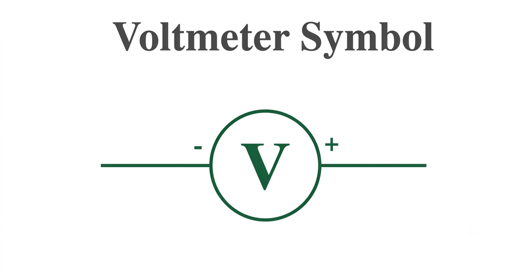
The symbol is used in electrical circuit diagrams to identify the position where voltage is measured.
Voltmeter Diagram and Connection
A voltmeter is always connected in parallel with the electrical component across which the potential difference is measured.
The following diagram illustrates how a voltmeter is connected in parallel across an electrical component to measure the potential difference.
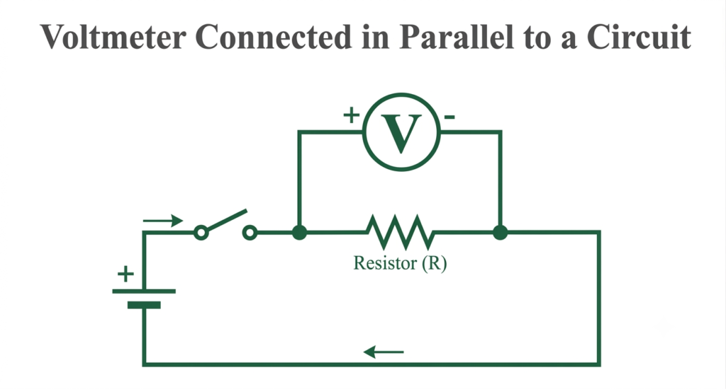
For example, to measure the voltage across a resistor, connect one voltmeter terminal to each end of the resistor.
The two terminals of the voltmeter are connected to points having different electrical potentials.
In a DC circuit, the positive terminal of the voltmeter is connected to the higher-potential point, and the negative terminal is connected to the lower-potential point.
In an AC circuit, the meter measures the alternating voltage, so the test connections generally do not require polarity selection.
Parts of a Voltmeter
The construction of a voltmeter depends on whether it is an analog or digital instrument. However, most voltmeters contain the following functional components.
1. Display or Indicating System
The display indicates the measured voltage.
In an analog voltmeter, a pointer moves over a calibrated scale to show the voltage value. In a digital voltmeter, an electronic display shows the measured voltage numerically.
2. Measuring Mechanism
The measuring mechanism detects the applied voltage and produces an indication proportional to the measured quantity.
In an analog instrument, this may involve a moving coil, moving iron element, or electrostatic mechanism.
3. Series Resistance (Multiplier)
A high-value resistance is connected in series with a sensitive measuring movement to extend its voltage-measuring range.
This resistance is commonly called a multiplier.
It limits the current flowing through the measuring mechanism and allows the instrument to measure higher voltages.
4. Input Terminals
The input terminals provide connections for the test leads or probes.
Generally, the red terminal is used for positive voltage and the black terminal for common or negative connections.
5. Range Selector Switch
A range selector allows the operator to select the appropriate voltage range.
For example, a multirange voltmeter may have 2 V, 20 V, 200 V, and 1,000 V ranges.
6. Internal Electronic Circuit
Digital voltmeters contain electronic circuits that process the input voltage.
These may include signal-conditioning circuits, amplifiers, filters, and analog-to-digital converters (ADCs).
7. Power Supply
Analog passive measuring mechanisms may not require an external power source for measurement. Digital voltmeters generally require an internal battery or external power supply to operate their electronic circuitry.
Voltmeter Formula
A voltmeter is commonly constructed by connecting a high resistance in series with a galvanometer or sensitive moving-coil measuring mechanism.
The series resistance is known as the voltmeter multiplier resistance.
The total voltage applied to the voltmeter is equal to the voltage drop across the series resistance plus the voltage across the measuring mechanism.
According to Ohm’s law:
Where:
- = Maximum voltage to be measured
- = Full-scale deflection current of the meter movement
- = Series multiplier resistance
- = Voltage across the meter movement at full-scale deflection
Since:
The voltmeter equation becomes:
Therefore, the required series resistance is:
Where is the internal resistance of the measuring movement.
Numerical Example: Calculate Voltmeter Multiplier Resistance
A galvanometer has an internal resistance of 100 Ω and a full-scale deflection current of 1 mA. Calculate the series resistance required to convert it into a 10 V voltmeter.
Given:
Using the formula:
Substituting the values:
Therefore, a series resistance of 9.9 kΩ is required to convert the galvanometer into a 10 V voltmeter.
Working Principle of Voltmeter
The working principle of a voltmeter depends on its construction and measuring mechanism.
A basic analog voltmeter operates by producing a deflecting effect proportional to the voltage applied across its terminals.
In a PMMC-based voltmeter, the applied voltage causes a small current to flow through the moving coil and its series resistance. The current produces a magnetic torque that moves the pointer over the calibrated scale.
The series resistance limits the current to a safe value.
The deflection of the pointer is proportional to the applied DC voltage because the current through the moving coil is proportional to voltage.
For a PMMC voltmeter:
Where:
- = Current through the moving coil
- = Applied voltage
- = Moving coil resistance
- = Series resistance
Since the resistance remains constant, the current varies directly with the applied voltage.
In a digital voltmeter, the input voltage is processed by an electronic measuring circuit and converted into a digital value using an analog-to-digital converter.
The measured value is then displayed numerically.
Types of Voltmeter
Voltmeters are classified according to their construction, operating principle, and measuring method.
The main types include:
- Analog voltmeter
- Digital voltmeter
- Permanent Magnet Moving Coil (PMMC) voltmeter
- Moving Iron (MI) voltmeter
- Rectifier-type voltmeter
- Electrostatic voltmeter
- Electrodynamometer-type voltmeter
- Electronic or amplified voltmeter
Let’s understand each type.
1. Analog Voltmeter
An analog voltmeter indicates the measured voltage through the movement of a pointer over a calibrated scale.
It generally consists of a measuring mechanism and a series multiplier resistance.
When voltage is applied across its terminals, the measuring mechanism produces a deflecting torque. The pointer moves until the deflecting torque balances the controlling torque.
The pointer position indicates the applied voltage.
Depending on the measuring mechanism, analog voltmeters can be designed for AC or DC voltage measurement.
Advantages:
- Simple construction.
- Continuous indication of changing voltage.
- Does not require a numerical display.
- Useful for observing gradual voltage variations.
Disadvantages:
- Reading errors may occur due to parallax.
- Mechanical movement can be affected by vibration.
- Generally offers lower resolution than digital instruments.
2. Digital Voltmeter (DVM)
A digital voltmeter displays the measured voltage directly in numerical form.
It uses electronic circuits to process the input voltage and convert it into a digital reading.
A typical digital voltmeter contains an input attenuator, signal-conditioning circuit, analog-to-digital converter, control circuit, and digital display.
Working:
- The input voltage is applied to the measuring terminals.
- The input circuit conditions the voltage to a suitable level.
- The analog-to-digital converter converts the analog signal into digital data.
- The electronic circuit processes the converted value.
- The voltage reading appears on the display.
Digital voltmeters are available for both AC and DC measurements.
Advantages:
- Easy-to-read numerical display.
- High resolution in suitable models.
- No pointer-reading or parallax error.
- High input impedance in many designs.
- Compact construction.
Applications:
- Electrical laboratories.
- Electronic circuit testing.
- Battery voltage measurement.
- Industrial maintenance.
- Power supply testing.
3. Permanent Magnet Moving Coil (PMMC) Voltmeter
A permanent magnet moving coil voltmeter operates on the principle of interaction between the magnetic field of a permanent magnet and the magnetic field produced by current flowing through a moving coil.
It consists of a lightweight coil placed between the poles of a permanent magnet.
When DC voltage is applied, a small current flows through the coil and produces a deflecting torque. The coil and attached pointer move over a calibrated scale.
The deflection is directly proportional to the current flowing through the coil and, therefore, to the applied voltage.
A high resistance is connected in series with the coil to convert the instrument into a voltmeter.
Important characteristics:
- Primarily used for DC voltage measurement.
- Uniform scale.
- High sensitivity.
- Good accuracy.
- Low power consumption.
A PMMC movement cannot directly measure AC voltage because the alternating current reverses direction every half-cycle, causing the average deflecting torque to become zero.
4. Moving Iron (MI) Voltmeter
A moving iron voltmeter works on the principle of magnetic attraction or repulsion produced by current flowing through a fixed coil.
It contains a fixed coil and a movable soft-iron element attached to a pointer.
When voltage is applied, current flows through the coil and produces a magnetic field. The magnetic field magnetizes the iron element, causing it to move and produce pointer deflection.
The deflecting torque is approximately proportional to the square of the current.
For a voltmeter having constant impedance:
Since the torque is independent of current direction, a moving iron voltmeter can measure both AC and DC voltage.
Types of moving iron instruments:
- Attraction-type moving iron instrument.
- Repulsion-type moving iron instrument.
Advantages:
- Can measure AC and DC voltage.
- Simple and rugged construction.
- Suitable for electrical power applications.
- Relatively economical.
Disadvantages:
- Non-uniform scale.
- Lower accuracy compared with many PMMC instruments.
- Affected by hysteresis and frequency variations.
- Higher power consumption than sensitive PMMC instruments.
5. Rectifier-Type Voltmeter
A rectifier-type voltmeter is used to measure AC voltage using a rectifier circuit and a PMMC measuring mechanism.
The rectifier converts the alternating input voltage into a unidirectional current. The PMMC movement then responds to the rectified current and indicates the voltage.
Most conventional rectifier-type AC voltmeters are calibrated to display the RMS value of a sinusoidal waveform based on its average rectified value.
However, when the waveform is distorted or nonsinusoidal, the reading may differ from the true RMS value unless the instrument is specifically designed for that purpose.
Applications:
- AC voltage measurement.
- Electronic testing.
- Communication equipment.
- Laboratory measurements.
6. Electrostatic Voltmeter
An electrostatic voltmeter works on the principle of electrostatic attraction or repulsion between charged electrodes.
When a voltage is applied between two electrodes, an electrostatic force is produced. This force causes mechanical movement that is indicated by a pointer.
The electrostatic force depends on the square of the applied voltage.
Because its operation does not depend on current flowing through a magnetic coil, an electrostatic voltmeter draws very little current from the circuit.
Applications:
- High-voltage measurement.
- Laboratory testing.
- Electrical insulation research.
- Measurement of high potential differences.
7. Electrodynamometer-Type Voltmeter
An electrodynamometer voltmeter works on the interaction between the magnetic fields produced by fixed and moving coils.
It consists of fixed coils and a movable coil connected in a suitable arrangement.
When voltage is applied, currents flow through the coils and produce a deflecting torque. The resulting pointer movement indicates the applied voltage.
These instruments can be designed for AC and DC measurement.
They are also used in precision electrical measurements, although their construction is more complex than that of ordinary moving iron instruments.
8. Electronic or Amplified Voltmeter
An electronic voltmeter uses an amplifier in its input circuit to measure very small voltage signals.
The amplifier increases the signal level before it is processed by the measuring mechanism.
These instruments generally provide high input impedance and are useful when measuring low-level signals without significantly loading the circuit.
Applications:
- Electronic laboratories.
- Low-voltage signal measurement.
- Sensor testing.
- Amplifier circuit testing.
- Instrumentation systems.
Why Is a Voltmeter Connected in Parallel?
A voltmeter is connected in parallel because its purpose is to measure the potential difference between two points of an electrical component.
When two components are connected in parallel, the potential difference across them is the same.
Therefore, connecting a voltmeter across a component allows it to measure the voltage across that component directly.
Another important reason is the high internal resistance of the voltmeter.
A practical voltmeter is designed to draw very little current. Consequently, it has a negligible effect on the current flowing through the main circuit.
If a voltmeter were connected in series, its high resistance would significantly reduce the circuit current and could disturb normal circuit operation.
For an ideal voltmeter:
Where is the internal resistance of the voltmeter.
An ideal voltmeter draws zero current from the circuit.
How to Use a Voltmeter?
The procedure for using a voltmeter depends on whether the voltage being measured is AC or DC.
Before connecting the instrument, always check its voltage rating, input terminals, and measurement category.
Steps to Measure Voltage Using a Voltmeter
Step 1: Identify the type of voltage
Determine whether the circuit operates on AC or DC voltage.
For example, batteries provide DC voltage, whereas household electrical supplies provide AC voltage.
Step 2: Select the appropriate voltage range
Set the meter to the AC voltage or DC voltage function.
If the approximate voltage is unknown, select a range higher than the expected voltage when using a manually ranged instrument.
Step 3: Connect the test leads
Insert the black lead into the COM terminal and the red lead into the voltage (V) terminal.
Step 4: Connect the voltmeter in parallel
Place the two probes across the component or supply whose voltage is to be measured.
For DC measurement, observe the correct polarity.
Step 5: Read the measured voltage
Observe the pointer position in an analog voltmeter or the numerical value displayed on a digital voltmeter.
Step 6: Interpret the reading
Compare the measured voltage with the rated or expected voltage of the equipment.
If the reading is outside the specified range, investigate the possible causes.
Safety precautions:
- Never connect a voltmeter across a circuit using its current-measurement input.
- Do not exceed the instrument’s maximum voltage rating.
- Use appropriately rated probes and protective equipment.
- Avoid touching exposed conductive probe tips.
- For industrial and high-voltage measurements, use suitable instruments and follow approved electrical safety procedures.
Applications and Uses of Voltmeter
Voltmeters are used in almost every field involving electrical and electronic systems.
Some important applications are discussed below.
1. Electrical Power Systems
Voltmeters are used to measure voltage in power generation, transmission, and distribution systems. They help monitor supply voltage and identify abnormal voltage conditions.
2. Electrical Machines
They are used to measure the terminal voltage of motors, generators, transformers, and other electrical equipment.
3. Battery Testing
A voltmeter helps check the terminal voltage of batteries used in automobiles, UPS systems, emergency power supplies, and solar installations.
4. Electronic Circuit Testing
Engineers use voltmeters to measure voltage at different points in electronic circuits to verify circuit operation and identify faults.
5. Industrial Maintenance
Voltmeters help maintenance engineers check the voltage of electrical panels, control circuits, power supplies, and industrial equipment.
6. Laboratory Experiments
They are used in electrical and electronics laboratories to measure potential differences and verify experimental results.
7. Power Quality Monitoring
Specialized voltage-measuring instruments help identify voltage fluctuations, voltage drops, unbalance, and other electrical supply problems.
8. Renewable Energy Systems
Voltmeters are used to monitor the output voltage of solar panels, battery banks, charge controllers, and inverters.
Characteristics of an Ideal Voltmeter
An ideal voltmeter should have the following characteristics:
- Infinite internal resistance: It should draw no current from the circuit.
- High sensitivity: It should detect very small changes in voltage.
- High accuracy: Its measured value should closely match the actual voltage.
- High resolution: It should be capable of displaying small voltage variations.
- No loading effect: It should not disturb the circuit being tested.
- Fast response: It should respond quickly to changes in the input voltage.
- Stable operation: Its reading should not change unnecessarily due to temperature or environmental variations.
In practice, no voltmeter is perfectly ideal, but modern digital instruments are designed to achieve many of these characteristics.
Difference Between Voltmeter and Ammeter
A voltmeter and an ammeter are electrical measuring instruments used to determine different electrical quantities.
A voltmeter measures the potential difference between two points, whereas an ammeter measures the current flowing through an electrical circuit.
The following table explains their major differences.
| Basis | Voltmeter | Ammeter |
| Measures | Voltage | Current |
| SI unit | Volt (V) | Ampere (A) |
| Circuit connection | Parallel | Series |
| Internal resistance | Very high | Very low |
| Ideal resistance | Infinite | Zero |
| Main purpose | Measures potential difference | Measures electric current |
| Circuit symbol | V inside a circle | A inside a circle |
| Basic construction | Measuring movement with series resistance | Measuring movement with shunt resistance |
Both instruments are essential for electrical testing, troubleshooting, and monitoring.
Conclusion
A voltmeter is an essential electrical measuring instrument used to measure the potential difference between two points in a circuit. It is connected in parallel with the component under test and has high internal resistance to minimize its effect on circuit operation.
Different types of voltmeters, including PMMC, moving iron, digital, rectifier, and electrostatic instruments, are available for different measurement requirements.
Understanding the working principle, construction, types, and correct connection of a voltmeter is important for electrical engineers, technicians, students, and anyone involved in electrical testing and maintenance.
Read Next:
- Null Type Instrument: Principle, Example, and Key Advantages
- Types of Measuring Instruments in Electrical Engineering
- Integrating Instruments: Classifications, Advantage and Applications
- Digital Instruments: Definition, Characteristics, Construction, Advantages, and Disadvantages
- Analog Instruments: Definition, Classification, and Working Principle
- Ammeter: Definition, Symbol, Working Principle, Types and Applications