Frequency is an important parameter in electrical and electronic systems. It indicates how many times a periodic signal completes one full cycle in one second. Frequency measurement is essential for testing AC power supplies, electrical machines, electronic circuits, communication systems, and signal generators.
But how is frequency measured in practice?
Frequency can be measured by determining the time taken by a periodic signal to complete one cycle and calculating its reciprocal. Instruments such as frequency counters, digital multimeters, and oscilloscopes are commonly used for this purpose. For digital signals, electronic counters can also measure the number of pulses received during a known time interval.
In this article, we will explain how frequency is measured, the instruments used, different measurement methods, practical examples, and factors affecting measurement accuracy.
What Is Frequency?
Frequency is the number of complete cycles of a periodic waveform occurring in one second.
It is represented by the symbol f and measured in hertz (Hz).
One hertz means that a signal completes one full cycle per second.
For example:
- A 50 Hz AC supply completes 50 cycles every second.
- A 60 Hz AC supply completes 60 cycles every second.
- A 1,000 Hz signal completes 1,000 cycles every second.
The frequency of a periodic signal depends on how quickly it repeats its waveform. A signal that repeats more frequently has a higher frequency.
Frequency Formula
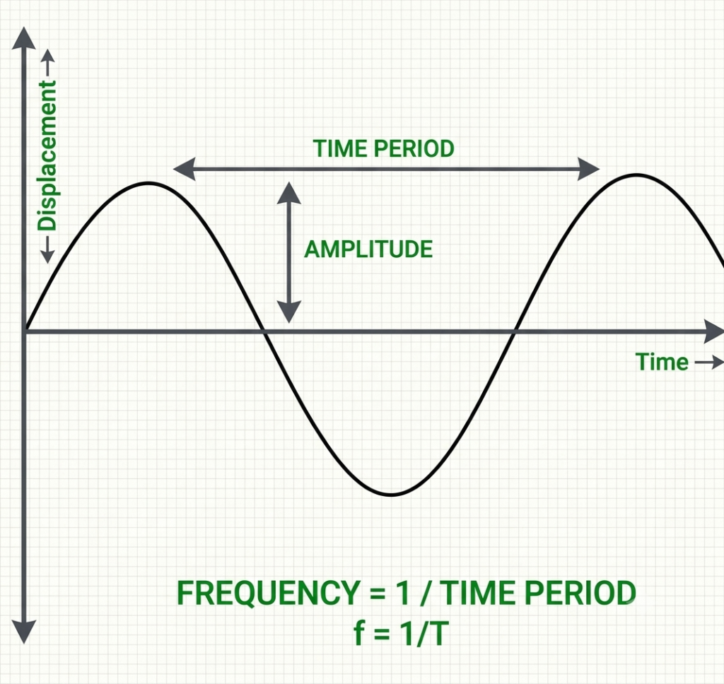
Frequency is the reciprocal of the time period.
Where:
- = Frequency in hertz (Hz)
- = Time period in seconds (s)
Similarly, the time period can be calculated as:
Example:
Suppose an AC waveform completes one cycle in 20 milliseconds. Calculate its frequency.
Given:
Using the frequency formula:
Therefore, the frequency of the waveform is 50 Hz.
Units of Frequency
The standard SI unit of frequency is the hertz (Hz). However, larger frequency values are commonly expressed using kilohertz, megahertz, and gigahertz.
| Unit | Symbol | Equivalent |
| Hertz | Hz | 1 cycle/second |
| Kilohertz | kHz | 1,000 Hz |
| Megahertz | MHz | 1,000,000 Hz |
| Gigahertz | GHz | 1,000,000,000 Hz |
| Unit | Symbol | Equivalent |
|---|---|---|
| Hertz | Hz | 1 cycle/second |
| Kilohertz | kHz | 1,000 Hz |
| Megahertz | MHz | 1,000,000 Hz |
| Gigahertz | GHz | 1,000,000,000 Hz |
Frequency can also be expressed in revolutions per minute (RPM) for rotating machines and cycles per minute for certain mechanical applications.
For rotating equipment:
Where:
- = Rotational frequency in revolutions per second (Hz)
- = Rotational speed in RPM
For example, a motor rotating at 1,500 RPM has a rotational frequency of:
Note that rotational frequency is different from the electrical supply frequency of an AC motor.
How Is Frequency Measured?
Frequency is generally measured using one of two basic approaches:
- Measuring the time period of a waveform.
- Counting the number of cycles or pulses within a known time interval.
The appropriate method depends on the signal frequency, waveform shape, required accuracy, and measurement instrument.
1. Measuring Frequency Using the Time Period Method
This method determines frequency by measuring the time required for one complete cycle of a periodic signal.
First, identify two consecutive points having the same phase, such as two successive rising zero crossings or rising edges. Measure the time between these points to obtain the time period.
Then calculate frequency using:
For better accuracy, the time interval can be measured over several cycles.
If (n) complete cycles occur during a measured interval (t), then:
Example:
Suppose an oscilloscope shows that 10 complete cycles of a waveform occur in 0.2 seconds.
Given:
Therefore:
The measured frequency is 50 Hz.
This method is particularly useful for measuring low-frequency signals and checking waveform frequency using an oscilloscope.
2. Measuring Frequency Using the Frequency Counting Method
A frequency counter measures frequency by counting the number of input signal cycles received during a precisely controlled time interval.
The instrument uses an accurate internal clock or timebase to establish the measurement interval.
The frequency is calculated as:
Where:
- (N) = Number of input cycles counted
- (t) = Measurement time in seconds
Example:
A frequency counter records 5,000 cycles during a measurement interval of 1 second.
Therefore, the input signal frequency is 5 kHz.
This method is widely used for measuring medium- and high-frequency electronic signals.
Instruments Used to Measure Frequency
Different instruments are used to measure frequency depending on the application and required accuracy.
The commonly used instruments are:
1. Frequency Counter
A frequency counter is an electronic instrument specifically designed to measure the frequency of periodic signals.
It counts the number of cycles received at its input during a known time interval. Its internal timebase provides the reference for calculating frequency.
Working principle:
- The input signal is applied to the frequency counter.
- The input circuit conditions the signal and generates suitable pulses.
- An electronic gate opens for a precisely controlled time interval.
- The counter counts the pulses received during this interval.
- The instrument calculates and displays the frequency.
For example, if the counter detects 10,000 pulses in one second, it displays 10 kHz.
Applications:
- Testing signal generators.
- Measuring oscillator frequency.
- Checking electronic circuits.
- Testing communication equipment.
- Measuring high-frequency signals.
2. Digital Multimeter (DMM)
Many digital multimeters include a frequency measurement function.
To measure frequency, connect the meter probes across the signal source or test points according to the manufacturer’s instructions. Select the frequency (Hz) function and read the displayed value.
The meter detects the periodic changes in the input signal and determines its frequency electronically.
A digital multimeter is useful for measuring the frequency of AC voltage signals in electrical and electronic circuits.
However, its measurement range and accuracy depend on the particular model.
Applications:
- Measuring AC supply frequency.
- Testing electrical equipment.
- Checking inverter output frequency.
- Troubleshooting electronic circuits.
3. Cathode Ray Oscilloscope (CRO)
A cathode ray oscilloscope displays an electrical signal as a waveform against time.
Frequency can be calculated by measuring the horizontal distance occupied by one complete cycle and multiplying it by the selected time-base setting.
The time period is:
Frequency is:
Example:
Suppose one complete waveform cycle occupies 4 horizontal divisions, and the oscilloscope time-base setting is 5 ms/division.
Then:
Therefore:
The frequency of the waveform is 50 Hz.
An oscilloscope is particularly useful because it allows the operator to observe waveform shape, amplitude, noise, distortion, and frequency simultaneously.
4. Digital Storage Oscilloscope (DSO)
A digital storage oscilloscope (DSO) samples an input signal using an analog-to-digital converter and stores the resulting waveform as digital data.
It can calculate frequency automatically using the measured time between corresponding waveform points.
The operator can also use cursors to measure the time period manually.
DSOs are widely used in electronic testing, power electronics, embedded systems, and industrial troubleshooting.
5. Analog Frequency Meter
An analog frequency meter measures the frequency of an AC signal and indicates the result using a pointer moving over a calibrated scale.
Depending on the instrument design, it may operate using a vibrating reed, electrical resonance, or a ratio-based measuring mechanism.
Vibrating-reed frequency meters are commonly associated with power-frequency measurement.
They are useful for checking whether an AC supply operates close to its rated frequency.
Methods of Measuring Digital Signal Frequency
Digital signals are generally measured by detecting their rising or falling edges. Electronic counters use these transitions to determine the number of cycles.
Two commonly used counter techniques are direct frequency measurement and reciprocal or period measurement.
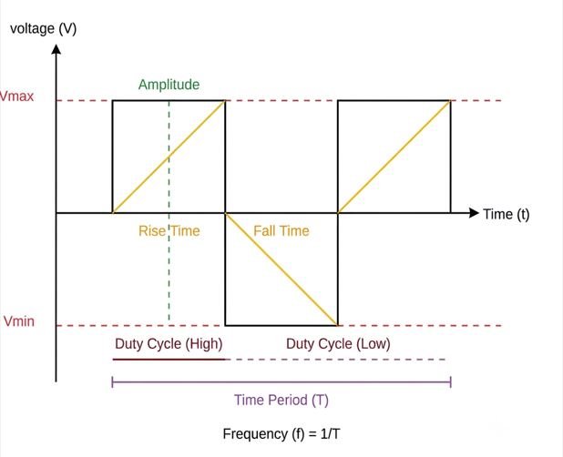
1. Direct Frequency Measurement
In direct frequency measurement, the instrument counts the number of input signal pulses during a known gate time.
The relationship is:
Where:
- = Number of pulses counted
- = Gate time in seconds
For example, if 20,000 pulses are counted in a gate time of 2 seconds:
Therefore, the frequency is 10 kHz.
A longer gate time generally improves counting resolution because more pulses are counted.
However, it also increases the measurement time.
2. Reciprocal Frequency Measurement
Reciprocal frequency measurement determines the time taken by an input signal to complete one or more cycles.
Instead of counting input pulses during a fixed gate interval, the instrument counts the ticks of a precise internal timebase between selected input signal edges.
If (M) internal clock pulses are counted during a measured interval , and the internal clock frequency is , then:
For a measurement covering (n) input cycles:
Substituting the measured time:
This technique can provide excellent resolution, particularly when measuring low-frequency signals.
How to Measure Frequency Using an Oscilloscope
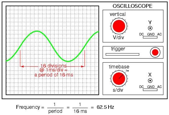
An oscilloscope is one of the most practical instruments for measuring the frequency of an electrical waveform.
Follow these steps:
- Connect the oscilloscope probe to the signal being measured.
- Connect the probe ground to the appropriate circuit reference.
- Adjust the vertical scale (volts/division) to display the waveform clearly.
- Adjust the horizontal time-base (seconds/division) to display several complete cycles.
- Identify two consecutive rising edges or equivalent points on the waveform.
- Measure the time period using the horizontal divisions.
- Calculate frequency using the reciprocal of the time period.
The frequency can also be obtained directly using the automatic measurement function available on most digital oscilloscopes.
Important: When measuring mains voltage or other potentially hazardous signals, use appropriately rated probes and suitable isolation or differential measurement arrangements. Never connect an ordinary grounded oscilloscope probe directly to a hazardous live conductor.
How to Measure AC Supply Frequency
AC supply frequency is commonly measured using a frequency meter, digital multimeter, or power quality analyzer.
In India, the nominal AC power supply frequency is 50 Hz.
To measure the frequency of an AC supply:
- Select a frequency meter or multimeter with a suitable frequency range.
- Check the instrument’s voltage and safety ratings.
- Connect the instrument according to its manufacturer’s instructions.
- Select the frequency measurement function.
- Read the displayed frequency.
A power quality analyzer can provide additional information, such as voltage, current, harmonics, and frequency variations.
For industrial installations, frequency measurement helps monitor generator performance, grid supply conditions, and the operation of electrical equipment.
What Factors Affect Frequency Measurement Accuracy?
The accuracy of frequency measurement depends on the instrument, input signal, measurement technique, and environmental conditions.
Important factors include:
1. Timebase Accuracy
A frequency counter relies on an internal clock or reference oscillator. Any error in the timebase directly affects the measured frequency.
2. Gate Time
In direct counting, a short gate time may result in greater counting uncertainty. Increasing the gate time generally improves resolution.
3. Signal Noise
Electrical noise can create unwanted transitions, resulting in incorrect pulse counts. Proper signal conditioning and shielding help reduce this problem.
4. Signal Amplitude
If the input signal amplitude is too low, the instrument may fail to detect its edges correctly. The signal must fall within the instrument’s specified input range.
5. Waveform Distortion
Distorted waveforms and harmonics can affect automatic frequency detection, particularly when the signal has multiple zero crossings or noisy transitions.
6. Measurement Range
Every instrument has a specified frequency range. Measuring outside this range can produce incorrect readings or no reading at all.
7. Trigger and Threshold Settings
Incorrect trigger levels can cause missed or additional transitions, affecting the calculated frequency.
Applications of Frequency Measurement
Frequency measurement is essential in electrical, electronic, and industrial applications.
Some common applications include:
- Power generation: Monitoring generator output frequency and grid frequency.
- Electric motors: Checking electrical supply frequency and rotational speed.
- Inverters and VFDs: Verifying output frequency and motor operating conditions.
- Communication systems: Measuring carrier and signal frequencies.
- Electronic circuits: Testing oscillators, timers, and clock generators.
- Power quality analysis: Monitoring frequency deviations in electrical distribution systems.
- Audio systems: Measuring sound signal frequencies and testing amplifiers.
- Industrial automation: Monitoring pulse frequency from sensors and encoders.
- Renewable energy: Checking inverter frequency and AC output performance.
Difference Between Frequency and Time Period
Frequency and time period describe the same periodic phenomenon from two different perspectives.
Frequency indicates the number of cycles completed per second, whereas the time period represents the time required to complete one cycle.
| Parameter | Frequency | Time Period |
| Definition | Number of cycles per second | Time taken to complete one cycle |
| Symbol | f | T |
| SI unit | Hertz (Hz) | Second (s) |
| Relationship | f = 1/T | T = 1/f |
| Effect of increase | Increases when time period decreases | Increases when frequency decreases |
For example, a 50 Hz signal has a time period of 20 milliseconds.
Conclusion
Frequency is measured by determining the number of cycles completed in a given time or by measuring the time period of a periodic waveform. The basic relationship is (f=1/T).
A frequency counter provides direct numerical measurement, while a digital multimeter and oscilloscope offer convenient methods for electrical and electronic testing. The selection of an instrument depends on the signal frequency, waveform characteristics, required accuracy, and measurement application.
Accurate frequency measurement is essential for maintaining the reliable operation of electrical power systems, motors, electronic circuits, communication equipment, and industrial control systems.
Read Next:
- Analog Frequency Meter: Working, Types and Applications
- Digital Frequency Meter: Working Principle, Block Diagram, Construction
- Vibrating Reed Frequency Meter: Principle, Construction, Working
- Electrical Resonance Type Frequency Meter
- Frequency Formula: Equations and Solved Examples
- Frequency Formula: Equations and Solved Examples