A Digital Frequency Meter is an electronic measuring instrument used to determine the frequency of periodic electrical signals and display the measured value in numerical form. It determines frequency by counting the number of signal cycles occurring within a precisely controlled time interval.
Unlike analog frequency meters, which indicate readings through pointer movement, digital instruments use electronic circuits, counters, and a display unit to provide easily readable frequency measurements. They are suitable for measuring signals ranging from low-frequency electrical supplies to high-frequency electronic and communication signals, depending on the instrument’s specifications.
Digital frequency meters are commonly used in electrical laboratories, electronic testing equipment, communication systems, industrial automation, generator testing, and research applications. Their measurement accuracy depends on factors such as the stability of the internal time-base oscillator, input signal conditioning, counting interval, and instrument resolution.
Block Diagram of a Digital Frequency Meter
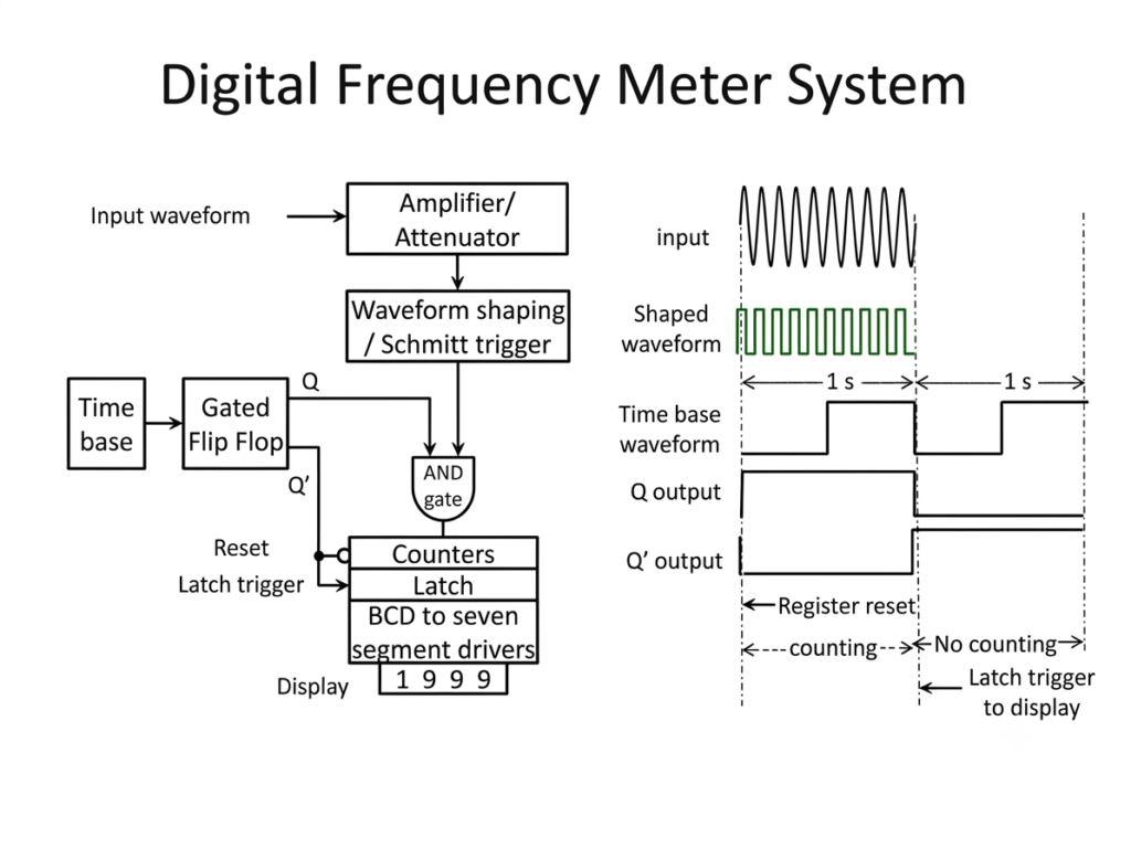
The block diagram of a digital frequency meter consists of several electronic sections that process the input signal and convert it into a numerical frequency reading.
The major blocks include:
- Input signal amplifier
- Wave-shaping circuit or Schmitt trigger
- Time-base generator
- Electronic gate
- Digital counter
- Display unit
Each section performs a specific function to ensure that the incoming signal is measured and displayed correctly.
Functions of Different Blocks
1. Input Signal Amplifier
The input amplifier receives the electrical signal whose frequency is to be measured. It increases or adjusts the signal amplitude to a suitable level for further processing. Input attenuation and protection circuits may also be provided to accommodate different signal levels.
2. Schmitt Trigger
The Schmitt trigger converts the incoming waveform into a clean digital square wave. It uses a defined switching threshold to produce sharp transitions, even when the input signal has a slowly changing waveform or some noise.
3. Time-Base Generator
The time-base generator produces accurate timing pulses using a stable reference oscillator, generally based on a crystal oscillator. These pulses establish the measurement interval during which the input signal cycles are counted.
4. Electronic Gate
The electronic gate controls the flow of pulses from the input signal to the counter. It opens for a predetermined time interval and closes when that interval expires.
5. Digital Counter
The digital counter counts the pulses received while the gate remains open. Since each pulse represents one complete input cycle, the total count is used to calculate the signal frequency.
6. Display Unit
The display unit receives the counter output and presents the measured frequency in numerical form. Depending on the instrument, the reading may be displayed in Hz, kHz, or MHz.
Working Principle of a Digital Frequency Meter
A digital frequency meter works on the principle of counting the number of cycles of an input signal during a precisely defined time interval. The measured frequency is obtained by dividing the total number of counted cycles by the measurement time.
When an electrical signal is applied to the instrument, the input circuit conditions the signal and passes it through a wave-shaping circuit. The Schmitt trigger converts the waveform into a sequence of digital pulses.
These pulses are applied to an electronic gate controlled by the time-base generator. The gate remains open for a known duration, allowing the counter to receive the input pulses. Once the measurement interval ends, the gate closes and the counter stops counting.
The number of pulses accumulated during this interval represents the frequency of the input signal. The result is then processed and displayed numerically.
Frequency measurement formula:
Where:
- = Frequency of the input signal in Hz
- = Number of pulses counted
- = Measurement time in seconds
Example:
Suppose a digital frequency meter counts 5,000 pulses during a measurement interval of 1 second.
Given:
Using the frequency formula:
Therefore, the frequency of the input signal is 5 kHz.
Digital Frequency Meter Circuit Diagram
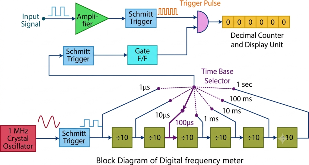
A digital frequency meter circuit uses electronic components to detect, process, count, and display the input signal frequency. Depending on its design, the circuit may contain operational amplifiers, Schmitt trigger ICs, logic gates, counter ICs, a crystal oscillator, and seven-segment display drivers.
The input signal is first converted into suitable logic pulses. These pulses are passed to the counter through a controlled gate. A reference clock determines how long the counter remains active. At the end of the counting period, the result is transferred to the display circuit.
The exact circuit arrangement varies according to the required frequency range, resolution, and measurement accuracy.
Basic Circuit for Frequency Measurement
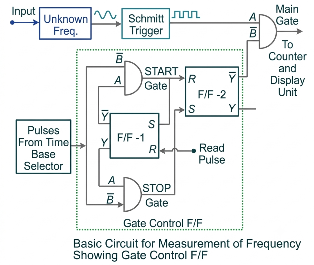
The basic circuit used in a digital frequency meter measures an unknown signal frequency by counting the number of pulses generated during a fixed time interval. The input signal is first applied to a Schmitt trigger, which converts it into a series of positive pulses. These pulses, known as counter signals, are connected to input A of the main gate.
At the same time, the time-base selector supplies positive timing pulses to the START and STOP gates. These signals control the operation of two flip-flops and determine the duration for which the main gate remains open.
Initially, flip-flop F/F-1 is in logic HIGH state. Its output enables the STOP gate, while its complementary output Y̅ remains at logic LOW and keeps the START gate disabled.
Since the STOP gate is enabled, timing pulses from the time-base selector pass through it and reach the SET input of F/F-2. This maintains F/F-2 in logic HIGH state. Its complementary output Y̅ remains LOW, preventing the main gate from passing any input pulses to the counter.
To initiate frequency measurement, a positive reset pulse is applied to F/F-1. This changes its output condition as follows:
Consequently, the STOP gate becomes disabled and the START gate becomes enabled. The same reset pulse is also applied to all decade counters, clearing their previous readings and setting the count to zero.
When the next timing pulse arrives, it passes through the START gate and resets F/F-2. Its output changes state, causing the complementary output Y̅ to become logic HIGH. This positive signal acts as the gating signal and enables the main AND gate.
At the same time, the START pulse sets F/F-1, changing its state from logic LOW to logic HIGH. This disables the START gate and enables the STOP gate. However, the main AND gate remains open, allowing pulses from the unknown input signal to reach the decade counter.
When the subsequent timing pulse arrives, it passes through the enabled STOP gate and sets F/F-2. Its complementary output Y̅ returns to logic LOW, disabling the main AND gate. As a result, the input signal is disconnected from the counter and pulse counting stops.
The counter now holds the number of input pulses received between two successive timing pulses from the time-base selector. If this time interval is one second, the total number of pulses counted directly represents the unknown frequency in Hertz (Hz).
The combination of two flip-flops and their associated START and STOP gates is known as a gate-control flip-flop circuit. It controls the measurement interval by determining when the main gate opens and closes.
Measurement Accuracy and Resolution
The accuracy of a digital frequency meter depends largely on the stability of its reference time base and the duration of the counting interval.
A longer measurement interval generally provides better frequency resolution because more input cycles are counted.
For example:
| Gate Time | Frequency Resolution |
| 0.01 second | 100 Hz |
| 0.1 second | 10 Hz |
| 1 second | 1 Hz |
| 10 seconds | 0.1 Hz |
For a conventional direct-counting frequency meter, the approximate count resolution is:
Where:
- = Frequency resolution
- = Measurement time
For measuring very low frequencies, some digital frequency meters use reciprocal counting or period measurement. In this method, the instrument measures the time taken by one or more complete cycles rather than simply counting cycles within a short gate interval.
For high-frequency signals, a prescaler may be used to divide the incoming frequency into a lower frequency that can be handled by the counter.
How to Extend the Frequency Range of a Digital Frequency Meter
A digital frequency meter measures frequency by counting the number of input signal cycles within a fixed time interval. However, direct counting has practical limitations at very high frequencies because the electronic counters have a maximum operating speed. When the input frequency exceeds this limit, the meter cannot count every pulse accurately.
To measure signals in the hundreds of megahertz or even the gigahertz range, special frequency-conversion and division techniques are used. These methods reduce the input frequency to a value that the counter can handle. Some commonly used techniques are explained below.
1. Prescaling Method
Prescaling is a technique used to measure high-frequency signals by dividing their frequency before applying them to the digital counter. A high-speed frequency divider reduces the input frequency by a fixed integer factor, such as 2, 4, 8, or 10.
The counter measures the reduced frequency, and the original input frequency is calculated by multiplying the measured value by the division factor.
For example, if a prescaler divides the input frequency by 10 and the counter measures 50 MHz, the original signal frequency is 500 MHz.
2. Heterodyne Conversion Method
The heterodyne method extends the measurement range by converting a high-frequency input signal into a lower-frequency signal.
In this technique, the unknown input signal is mixed with a signal generated by a local oscillator. The mixer produces sum and difference frequency components. The lower-frequency difference component is selected and applied to the digital frequency counter.
By measuring this intermediate frequency and knowing the local oscillator frequency, the original input frequency can be determined.
3. Transfer Oscillator Method
The transfer oscillator method is used to determine frequencies that are too high for direct measurement by a conventional digital counter.
A tunable low-frequency oscillator is adjusted until its harmonic frequency matches the unknown input frequency. This condition is identified using a zero-beat indication, which occurs when the frequency difference becomes zero.
The frequency of the low-frequency oscillator is then measured. The unknown high frequency is calculated by multiplying the oscillator frequency by the corresponding harmonic number.
4. Automatic Frequency Divider Method
An automatic frequency divider reduces a high-frequency input signal to a lower frequency using automatically controlled frequency-division circuits.
Depending on the circuit design, the input frequency may be divided by a factor such as 100 or 1,000. The resulting lower-frequency signal is then fed to the digital counter for measurement.
The original frequency is obtained by multiplying the measured frequency by the division ratio. This technique allows the meter to handle input signals that are beyond the operating range of its internal counter.
Advantages of a Digital Frequency Meter
The major advantages of a digital frequency meter are as follows:
- High accuracy: Provides precise frequency measurements when equipped with a stable time-base oscillator.
- Easy readability: Displays the measured value numerically, eliminating pointer-reading and parallax errors.
- Wide measurement range: Suitable models can measure frequencies ranging from very low values to several GHz.
- High resolution: Longer counting intervals and advanced measurement techniques allow fine frequency measurements.
- Fast measurement: Provides quick readings for many practical measurement applications.
- Data processing: Some models support data storage, remote monitoring, and computer interfacing.
- Automatic operation: Electronic circuits perform signal processing and frequency counting without manual calculations.
Disadvantages of a Digital Frequency Meter
Despite its advantages, a digital frequency meter has certain limitations:
- Power requirement: Electronic circuits require a suitable power supply for operation.
- Time-base dependency: Measurement accuracy depends on the stability and calibration of the reference oscillator.
- Counting error: Direct frequency counting has a resolution limitation associated with the measurement gate time.
- Input limitations: Signals outside the specified voltage, frequency, or waveform range may produce incorrect readings.
- Circuit complexity: Advanced instruments require more sophisticated electronic components and signal-processing circuits.
- Cost: High-accuracy instruments with extended frequency ranges and advanced features can be expensive.
Applications of a Digital Frequency Meter
Digital frequency meters are used in several electrical, electronic, and industrial applications where accurate frequency measurement is required.
1. Electrical Power Systems
Used to measure the frequency of AC supplies, alternators, generators, and power distribution systems. They help engineers monitor supply frequency and identify deviations from the rated value.
2. Communication Systems
Used for measuring the frequency of radio-frequency (RF) signals, transmitters, receivers, and communication equipment.
3. Electronic Testing Laboratories
Used to verify the output frequency of oscillators, function generators, signal generators, and electronic circuits.
4. Industrial Automation
Used to monitor pulse frequencies generated by sensors, encoders, and electronic control systems. Frequency measurements can help determine motor speed and machine operating conditions.
5. Research and Development
Used in electronic circuit development, frequency-response testing, oscillator calibration, and experimental measurements.
6. Sensor-Based Measurement Systems
Certain sensors convert physical quantities such as temperature, pressure, displacement, or vibration into frequency-related electrical signals. A digital frequency meter can measure these signals when the sensor and measurement system are designed for frequency-based output.
7. Radio and Television Equipment
Used for checking oscillator frequencies, carrier signals, and other frequency-dependent parameters in communication and broadcasting equipment.
Difference Between Analog and Digital Frequency Meter
| Parameter | Analog Frequency Meter | Digital Frequency Meter |
| Display | Moving pointer | Numerical display |
| Working principle | Electromagnetic or mechanical operation | Electronic pulse counting |
| Accuracy | Generally lower | Generally higher |
| Resolution | Limited by scale divisions | Depends on counting interval and design |
| Reading | Requires visual scale interpretation | Direct numerical reading |
| Construction | Electromechanical or resonant | Electronic circuits |
| Applications | Electrical panels and power systems | Laboratories, testing and communication systems |
Conclusion
A digital frequency meter is a useful electronic instrument for measuring the frequency of periodic electrical signals with high accuracy and convenient numerical indication. It operates by converting the input waveform into digital pulses and counting them over a precisely controlled time interval. The combination of signal-conditioning circuits, a time-base generator, an electronic gate, and a digital counter makes frequency measurement straightforward and reliable. Due to its accuracy, resolution, and versatility, it is widely used in electrical testing, communication systems, electronic laboratories, and industrial applications.
Read Next:
- Wattmeter: Working Principle, Types, Advantages, and Applications
- Induction Type Wattmeter: Construction, Working Principle, Diagram, and Torque Equation
- Electrodynamometer Type Wattmeter: Construction, Working Principle
- Wattmeter Connection: Diagram and Methods Explained
- Three Wattmeter Method: Three-Phase Power Measurement
- Analog Instruments: Definition, Classification, and Working Principle
- Null Type Instrument: Principle, Example, and Key Advantages
- Types of Measuring Instruments in Electrical Engineering
- Integrating Instruments: Classifications, Advantage and Applications
- Digital Instruments: Definition, Characteristics, Construction, Advantages, and Disadvantages
- Analog Frequency Meter: Working, Types and Applications