An Analog Frequency Meter is an important instrument in electrical engineering for monitoring frequency variations in AC power systems. It uses an indicating mechanism to translate changes in the electrical supply into visible pointer movement. Understanding its construction, working principle, types, and applications helps explain how this instrument supports frequency monitoring in generators, substations, and industrial electrical installations.
What Is an Analog Frequency Meter?
An analog frequency meter is an electrical measuring instrument used to determine the frequency of an alternating current (AC) supply. It indicates the measured frequency through a moving pointer that travels across a graduated scale. Unlike a digital frequency meter, which displays the reading numerically, an analog instrument provides a continuous visual indication of frequency variations.
The frequency of an AC electrical supply represents the number of complete cycles produced per second. It is measured in Hertz (Hz). For example, the standard power supply frequency is 50 Hz in India and several other countries, while some countries, including the United States, use 60 Hz.
Maintaining the rated frequency is important for the proper operation of electrical equipment. Changes in supply frequency can affect the speed of AC motors, generator operation, transformer performance, and the overall stability of an electrical power system.
An analog frequency meter converts changes in electrical frequency into mechanical movement. Depending on its construction, it may operate using vibrating reeds, electrodynamic mechanisms, or electrical resonance. The resulting movement produces a pointer indication corresponding to the measured frequency.
These instruments are commonly installed in generator control panels, power distribution boards, substations, power plants, and industrial electrical panels. Operators use them to monitor supply frequency and identify deviations from the rated operating value.
Although digital frequency meters offer greater measurement flexibility and convenient numerical displays, analog frequency meters remain useful in industrial applications. Their simple construction, direct visual indication, and robust design make them suitable for continuous monitoring. The movement of the pointer also helps operators observe gradual frequency fluctuations without repeatedly checking numerical readings.
Working Principle of an Analog Frequency Meter
An analog frequency meter works on the principle of electromagnetic interaction, mechanical resonance, or electrical resonance, depending on its construction. It converts the frequency of an alternating current (AC) supply into a mechanical movement that indicates the measured value on a calibrated scale.
In a conventional analog frequency meter, the AC supply is connected to the instrument’s input terminals. The applied voltage produces an electromagnetic effect or excites a resonant element inside the meter. When the supply frequency changes, the internal electrical or mechanical response also changes.
This variation moves the indicating mechanism, causing the pointer to settle at a position corresponding to the input frequency. The operator can then read the frequency directly in Hertz (Hz).
For example, when a frequency meter is connected to a 50 Hz AC supply, its pointer indicates approximately 50 Hz on the calibrated scale.
Working Principle of an Analog Frequency Meter
The moving-iron analog frequency meter operates on the principle that the currents flowing through two parallel circuits change differently when the supply frequency varies. One circuit is predominantly inductive, while the other has a comparatively non-inductive characteristic. The resulting change in magnetic fields determines the position of the indicating pointer.
The instrument consists of two coils, A and B, mounted with their magnetic axes at right angles to each other. A slender soft-iron pointer is pivoted at the centre of these coils. It aligns itself with the resultant magnetic field produced by the two coils. Unlike conventional moving-iron instruments, this frequency meter does not require a separate controlling spring to establish the pointer position.
The circuit diagram of an analog frequency meter is shown below.
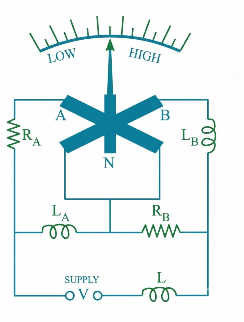
The electrical arrangement includes resistance and inductance components connected with the two coils. Coil A has resistance in series with it and inductance in parallel. Similarly, coil B has resistance in series and inductance in parallel. These components form a frequency-sensitive bridge circuit that is balanced at the designed supply frequency.
An additional series inductor is provided to reduce the effect of higher-frequency harmonics in the current waveform. This helps minimize errors in the frequency indication caused by waveform distortion.
Working of an Analog Frequency Meter
When an AC supply is applied to the instrument, currents flow through coils A and B. Both coils produce magnetic fields that act on the soft-iron pointer.
– At higher frequencies: The inductive reactance of increases as the supply frequency rises. This changes the current distribution in the two branches, with coil A carrying comparatively more current than coil B. Consequently, the magnetic field of coil A becomes stronger, and the iron pointer moves closer to its magnetic axis.
– At lower frequencies: The current through coil B becomes comparatively greater than the current through coil A. Its magnetic field therefore has a stronger influence on the soft-iron pointer, causing it to move towards the magnetic axis of coil B.
As the supply frequency changes, the relative strengths of the magnetic fields also change. The soft-iron pointer continuously adjusts its position according to the resultant magnetic field, indicating the corresponding frequency on the calibrated scale.
The instrument can be designed for either a narrow or a wide frequency measurement range by selecting suitable values of resistance and inductance in its circuit.
Features of an Analog Frequency Meter
- Mechanical indication: Displays frequency through a moving pointer and calibrated scale.
- Simple construction: Uses electromechanical or resonant operating principles.
- Continuous monitoring: Provides a visual indication of frequency variations.
- Rugged design: Suitable for installation in industrial electrical panels.
- Low maintenance: Generally requires minimal routine maintenance.
- Limited precision: Typically offers lower reading resolution than digital frequency meters.
Types of Analog Frequency Meters
Analog frequency meters are available in different designs depending on their operating principles. The commonly used types include the following.
Vibrating Reed Frequency Meter
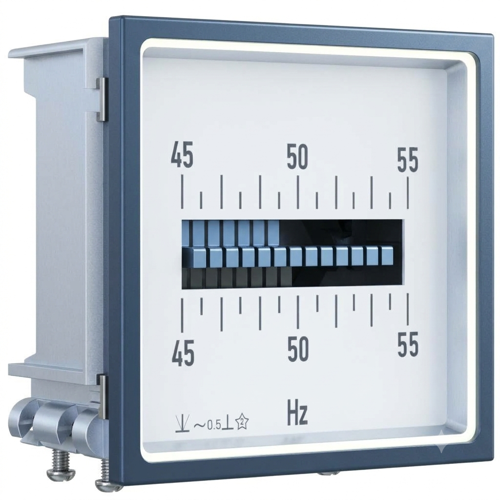
A vibrating reed frequency meter measures AC frequency using a series of thin metallic reeds. Each reed is mechanically adjusted to vibrate at a particular natural frequency.
When an AC supply is applied to the instrument, an alternating magnetic field produces vibrations in the reeds. The reed whose natural frequency is closest to the supply frequency vibrates with the greatest amplitude.
The frequency is identified by observing which reed vibrates most strongly. The reeds are marked with their corresponding frequency values, allowing the operator to determine the approximate supply frequency.
Features:
- Simple and robust construction.
- Suitable for measuring fixed power frequencies such as 50 Hz and 60 Hz.
- Does not require a conventional moving pointer.
- Provides an approximate frequency indication rather than a highly precise reading.
Applications:
- Generator frequency monitoring.
- Industrial electrical panels.
- Basic power supply frequency measurement.
Electrodynamic Frequency Meter
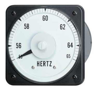
An electrodynamic frequency meter operates through the interaction of magnetic fields produced by current-carrying coils. It generally uses two coils connected through suitable electrical components so that their magnetic effects vary with supply frequency.
When the AC frequency changes, the current distribution and resulting electromagnetic torques also change. This causes the moving system and pointer to settle at a different position on the calibrated scale.
The pointer position indicates the corresponding frequency value.
Features:
- Uses electromagnetic operating principles.
- Provides direct pointer indication.
- Suitable for continuous frequency monitoring.
- Requires proper calibration for accurate readings.
Applications:
- Generator control panels.
- Industrial power distribution systems.
- Electrical testing and monitoring installations.
Resonance-Type Frequency Meter
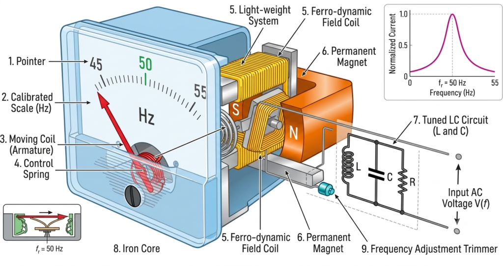
A resonance-type frequency meter measures frequency using the resonance phenomenon of an electrical circuit. It generally consists of an inductance (L) and capacitance (C) arranged to produce a resonant frequency.
The resonant frequency is determined by:
Where:
- = Resonant frequency in Hz
- = Inductance in henry (H)
- = Capacitance in farad (F)
When the frequency of the applied AC supply approaches the resonant frequency of the circuit, the electrical response changes. This variation is used by the instrument’s indicating mechanism to determine the frequency.
Features:
- Operates on the principle of electrical resonance.
- Provides frequency measurement over a designed operating range.
- Uses inductive and capacitive components.
- Requires suitable calibration for the intended frequency range.
Applications:
- Electrical testing laboratories.
- Frequency measurement circuits.
- Power system testing and inspection.
Advantages of Analog Frequency Meters
The major advantages of analog frequency meters include:
- Simple operation: The frequency reading can be observed directly from the calibrated scale.
- Continuous indication: Pointer movement makes it easy to observe gradual changes in frequency.
- Rugged construction: Many designs are suitable for industrial environments.
- No complex digital circuitry: Conventional electromechanical designs have relatively simple internal construction.
- Easy panel installation: Available in standard panel-mounted configurations.
- Low maintenance: Generally requires limited maintenance when operated within its specified ratings.
Limitations of Analog Frequency Meters
Despite their advantages, analog frequency meters have certain limitations.
- Lower accuracy: Their measurement accuracy is generally lower than that of modern digital instruments.
- Reading errors: Parallax and pointer positioning can introduce reading errors.
- Mechanical wear: Moving components may deteriorate over prolonged operation.
- Limited measurement range: Each instrument is designed for a specified frequency range.
- Slower response: Mechanical inertia can limit the response to rapid frequency changes.
- Calibration requirements: Periodic calibration may be necessary to maintain measurement accuracy.
Applications of Analog Frequency Meters
Analog frequency meters are particularly useful where operators need a continuous visual indication of AC supply frequency.
Common applications include:
- Power generation: Monitoring the output frequency of alternators and generators.
- Electrical substations: Checking the frequency of incoming and outgoing AC supplies.
- Industrial plants: Monitoring the frequency of electrical distribution systems.
- Generator synchronization: Observing frequency differences before synchronizing generators with a power system.
- Electrical laboratories: Demonstrating frequency measurement and resonance principles.
Important: An analog frequency meter used for generator synchronization provides frequency information, but synchronization also requires checking voltage magnitude, phase sequence, and phase-angle difference.
Conclusion
An analog frequency meter is an important electrical measuring instrument used to monitor the frequency of an AC supply. It operates through electromagnetic interaction, mechanical vibration, or electrical resonance, depending on its design.
Its simple construction, continuous pointer indication, and reliable operation make it useful in electrical panels, generators, substations, and industrial power systems. Although digital frequency meters offer greater accuracy and advanced measurement features, analog frequency meters remain valuable for routine monitoring and observing frequency variations in electrical installations.
Read Next:
- Wattmeter: Working Principle, Types, Advantages, and Applications
- Induction Type Wattmeter: Construction, Working Principle, Diagram, and Torque Equation
- Electrodynamometer Type Wattmeter: Construction, Working Principle
- Wattmeter Connection: Diagram and Methods Explained
- Three Wattmeter Method: Three-Phase Power Measurement
- Analog Instruments: Definition, Classification, and Working Principle
- Null Type Instrument: Principle, Example, and Key Advantages
- Types of Measuring Instruments in Electrical Engineering
- Integrating Instruments: Classifications, Advantage and Applications
- Digital Instruments: Definition, Characteristics, Construction, Advantages, and Disadvantages