A wattmeter connection determines how the instrument’s current coil and pressure coil are connected to an electrical circuit to measure power consumption. The correct connection is important for obtaining accurate readings and minimizing measurement errors caused by the power losses in the wattmeter coils.
In electrical engineering, a wattmeter is commonly used to measure the active power consumed by electrical loads such as motors, heaters, transformers, and other electrical equipment. For single-phase power measurement, two practical methods are used to connect the wattmeter: the pressure coil can be connected on the supply side or on the load side of the current coil.
This article explains the wattmeter connection diagrams, working principles, differences between the two methods, and how to select the appropriate connection for accurate power measurement.
What Is a Wattmeter Connection?
A wattmeter connection is the arrangement used to connect the instrument to an electrical circuit for measuring active power. A conventional electrodynamometer-type wattmeter has two main coils.
- Current coil (CC): Connected in series with the load so that it carries the load current. It has low resistance.
- Pressure coil (PC): Connected in parallel with the load or supply to measure the applied voltage. It has high resistance.
The wattmeter measures power based on the interaction between the magnetic fields produced by these coils. For a single-phase AC circuit, its ideal reading is:
Where:
- = active power in watts (W)
- = RMS voltage in volts (V)
- = RMS current in amperes (A)
- = load power factor
- = phase angle between voltage and current
The actual reading may include a small additional power loss associated with the wattmeter’s current coil or pressure coil, depending on the connection method.
Wattmeter Connection Diagram
There are two commonly discussed methods for connecting a wattmeter in a single-phase circuit.
Method 1: Pressure Coil Connected on the Supply Side
In this arrangement, the pressure coil is connected across the supply terminals, while the current coil is connected in series with the load.
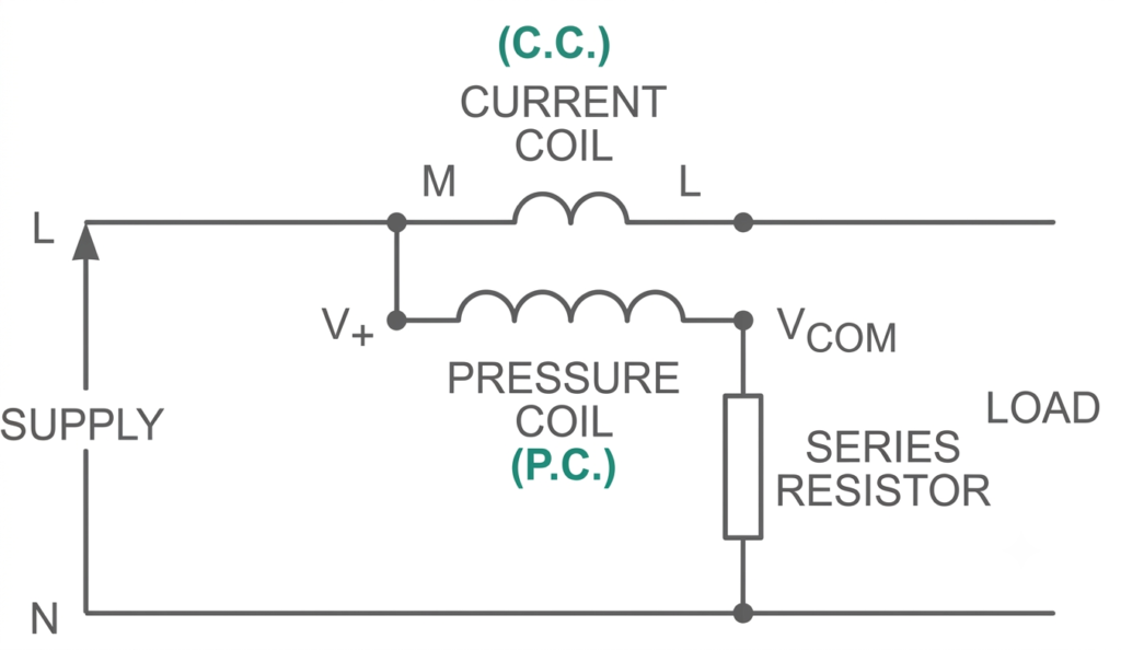
The pressure coil measures the supply voltage, which includes the voltage drop across the current coil and the voltage across the load.
The current coil carries the load current, and the pressure coil receives the supply voltage. Consequently, the wattmeter measures the load power along with the power loss in the current coil.
The wattmeter reading can be expressed as:
Where:
- = measured power
- = actual load power
- = load current
- = resistance of the current coil
The additional term represents the power dissipated in the current coil.
When is this connection preferred?
This connection is generally suitable for loads drawing relatively small current, where the current coil’s power loss is small compared with the load power. It is also useful when the pressure coil’s power consumption is significant relative to the load power and should be excluded from the reading.
Method 2: Pressure Coil Connected on the Load Side
In this arrangement, the current coil is connected on the supply side of the junction, and the pressure coil is connected directly across the load.
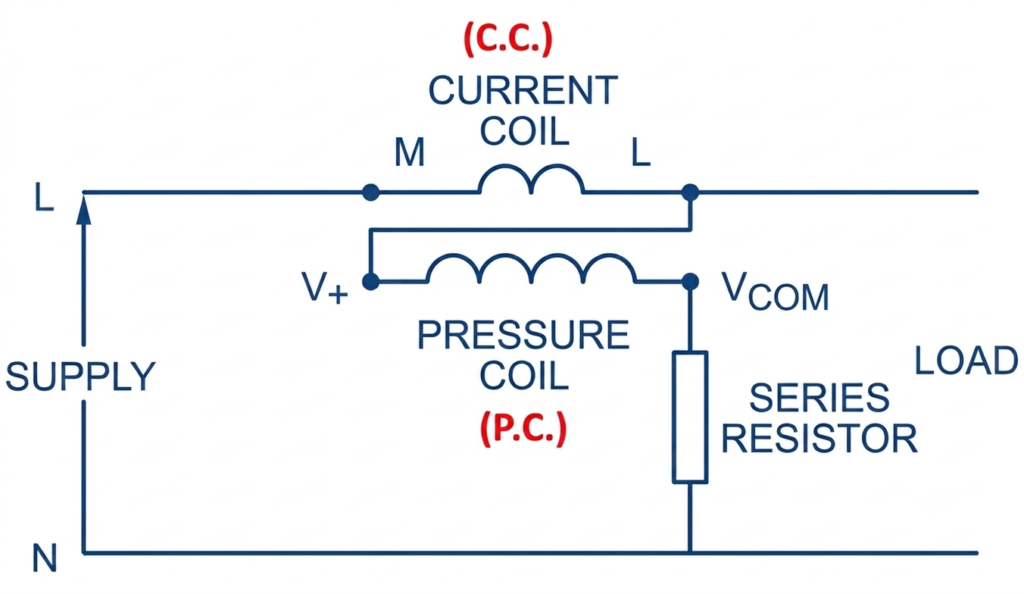
The pressure coil measures the voltage across the load, while the current coil carries the combined current drawn by the load and the pressure coil.
Because the current coil carries the pressure coil current in addition to the load current, the wattmeter reading includes the load power and the power consumed by the pressure coil.
The wattmeter reading can be expressed as:
Where:
- = measured power
- = actual load power
- = voltage across the load
- = effective resistance of the pressure coil circuit
The additional term represents the power consumed by the pressure coil circuit.
When is this connection preferred?
This connection is generally suitable for loads drawing relatively large current, provided the pressure coil’s power consumption is small compared with the load power. It avoids including the current coil’s power loss in the measured load power.
Difference Between the Two Wattmeter Connection Methods
| Feature | Method 1: Pressure coil on supply side | Method 2: Pressure coil across load |
| Pressure coil voltage | Supply voltage | Load voltage |
| Current coil current | Load current | Load current plus pressure coil current |
| Additional power included | Current coil loss | Pressure coil circuit loss |
| Measurement error | Due to current coil loss | Due to pressure coil power consumption |
| Generally preferred for | Relatively small load current | Relatively large load current |
| Main advantage | Pressure coil loss is excluded from the reading | Current coil loss is excluded from the reading |
The best connection depends on the relative sizes of the current coil loss, pressure coil power consumption, and load power. The load current alone does not determine which method will provide the smaller error in every circuit.
How to Select the Correct Wattmeter Connection
To select the appropriate wattmeter connection, compare the additional power included in each measurement.
For Method 1, the approximate measurement error is:
For Method 2, the approximate measurement error is:
Choose the connection that produces the smaller additional power relative to the actual load power, provided the instrument’s ratings and connection requirements are satisfied.
For example, when measuring a low-current load, the current coil loss may be negligible, making Method 1 suitable. When measuring a high-current load, Method 2 may be preferable if the pressure coil power consumption is comparatively small.
Precautions for Wattmeter Connection
Follow these precautions when connecting a wattmeter to an electrical circuit:
- Connect the current coil in series with the load.
- Connect the pressure coil in parallel with the appropriate supply or load terminals, according to the selected method.
- Check the rated voltage and current of the wattmeter before energizing the circuit.
- Observe the correct terminal polarity, especially when using DC wattmeters or instruments with marked terminals.
- Ensure that the connections are secure and that the instrument is suitable for the circuit’s AC or DC supply.
- Never connect a low-resistance current coil directly across a voltage source.
- De-energize the circuit before changing connections unless a suitable approved live-working procedure is in place.
Conclusion
The wattmeter connection affects the accuracy of electrical power measurement because the instrument coils consume a small amount of power themselves. When the pressure coil is connected on the supply side, the reading includes the current coil loss. When the pressure coil is connected across the load, the reading includes the pressure coil circuit’s power consumption.
Selecting the appropriate connection requires comparing these two sources of error. Understanding both methods helps electrical engineers and technicians measure active power more accurately in single-phase electrical circuits.
Read Next:
- Wattmeter: Working Principle, Types, Advantages, and Applications
- Induction Type Wattmeter: Construction, Working Principle, Diagram, and Torque Equation
- Two Wattmeter Method: Circuit Diagram, Working Principle, and Derivation
- Electrodynamometer Type Wattmeter: Construction, Working Principle, Torque Equation
- Three Wattmeter Method: Three-Phase Power Measurement