The two wattmeter method is a widely used technique for measuring total active power in a three-phase, three-wire AC electrical system. It uses two wattmeters connected to the supply lines to determine the combined power consumed by a three-phase load.
One of the main advantages of this method is that it can measure total three-phase power in both balanced and unbalanced loads without requiring a neutral connection. For a balanced load, the two wattmeter readings can also be used to calculate the power factor and reactive power.
The method is commonly used in electrical laboratories, industrial power systems, motor testing, and three-phase electrical measurements.
What Is the Two Wattmeter Method?
The two wattmeter method is a technique for measuring the total active power of a three-phase, three-wire circuit using two wattmeters.
Each wattmeter has two measuring circuits:
- Current coil (CC): Connected in series with one supply line to carry the line current.
- Pressure coil (PC): Connected between that line and a common third line to measure the corresponding line-to-line voltage.
The sum of the two wattmeter readings gives the total active power consumed by the three-phase load, whether the load is balanced or unbalanced, provided the circuit is a three-wire system and the connections are correct.
For a balanced load, the power factor and reactive power can also be calculated from the difference between the readings.
Circuit Diagram of the Two Wattmeter Method
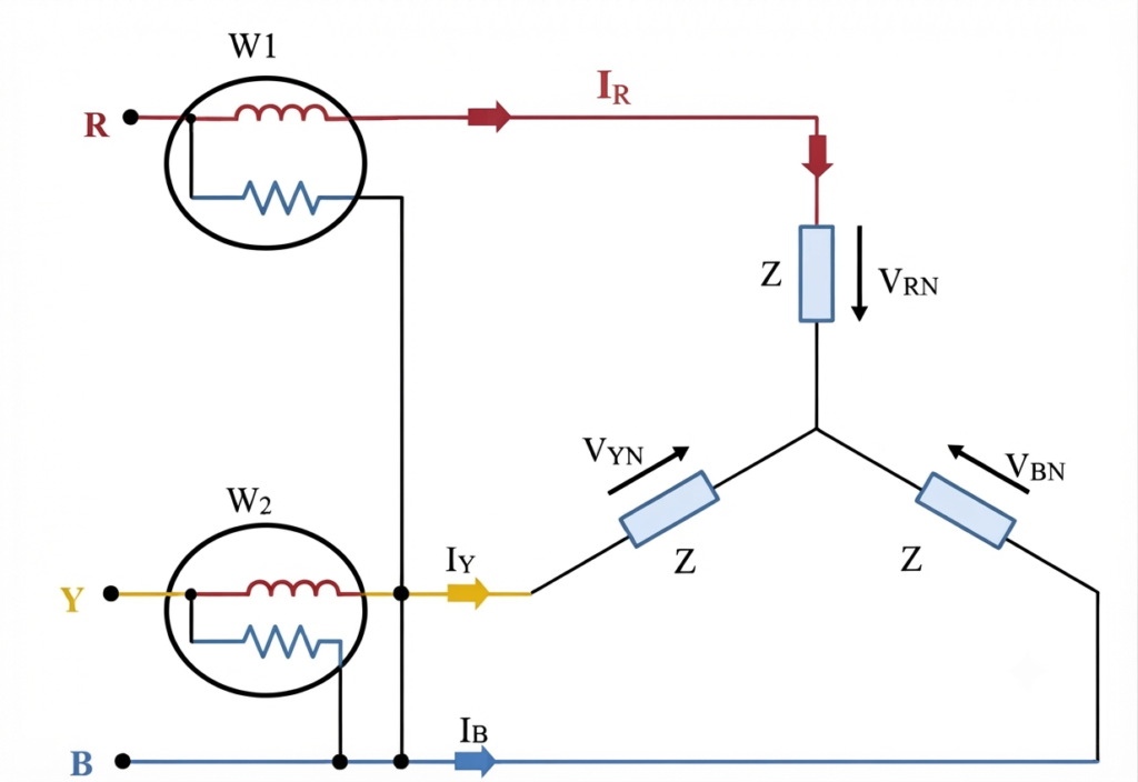
The circuit consists of two wattmeters, a three-phase supply, and the load being measured.
- Wattmeter has its current coil connected in the R line and its pressure coil connected between the R and B lines.
- Wattmeter has its current coil connected in the Y line and its pressure coil connected between the Y and B lines.
- The B line acts as the common connection for the two pressure coils.
- The three-phase load may be connected in star or delta, depending on the application.
The current coils carry their respective line currents, while the pressure coils measure line-to-line voltages. The resulting readings are added algebraically to determine the total active power.
Working Principle of the Two Wattmeter Method
The two wattmeter method works by measuring two components of power in a three-phase circuit. Each wattmeter responds to the current flowing through its current coil and the voltage applied across its pressure coil.
The operating procedure is as follows.
- Connect the current coil of the first wattmeter in one supply line and its pressure coil between that line and the common third line.
- Connect the second wattmeter in another supply line, with its pressure coil connected between that line and the same common line.
- Switch on the supply and allow the instruments to indicate their readings.
- Add the two readings algebraically to obtain the total active power.
The total power is:
Here, and are the signed readings of the two wattmeters. If a wattmeter indicates negative power, its reading must be included with a negative sign.
For a balanced three-phase load, the same readings can also be used to determine the power factor and reactive power.
Derivation of the Two Wattmeter Method
Consider a balanced three-phase load supplied by a three-phase AC source. Let the load current lag its corresponding phase voltage by an angle .
Let:
- = Line voltage
- = Line current
- = Load power-factor angle
- = Reading of the first wattmeter
- = Reading of the second wattmeter
- = Total active power
Assume the wattmeters are connected according to the circuit arrangement described above.
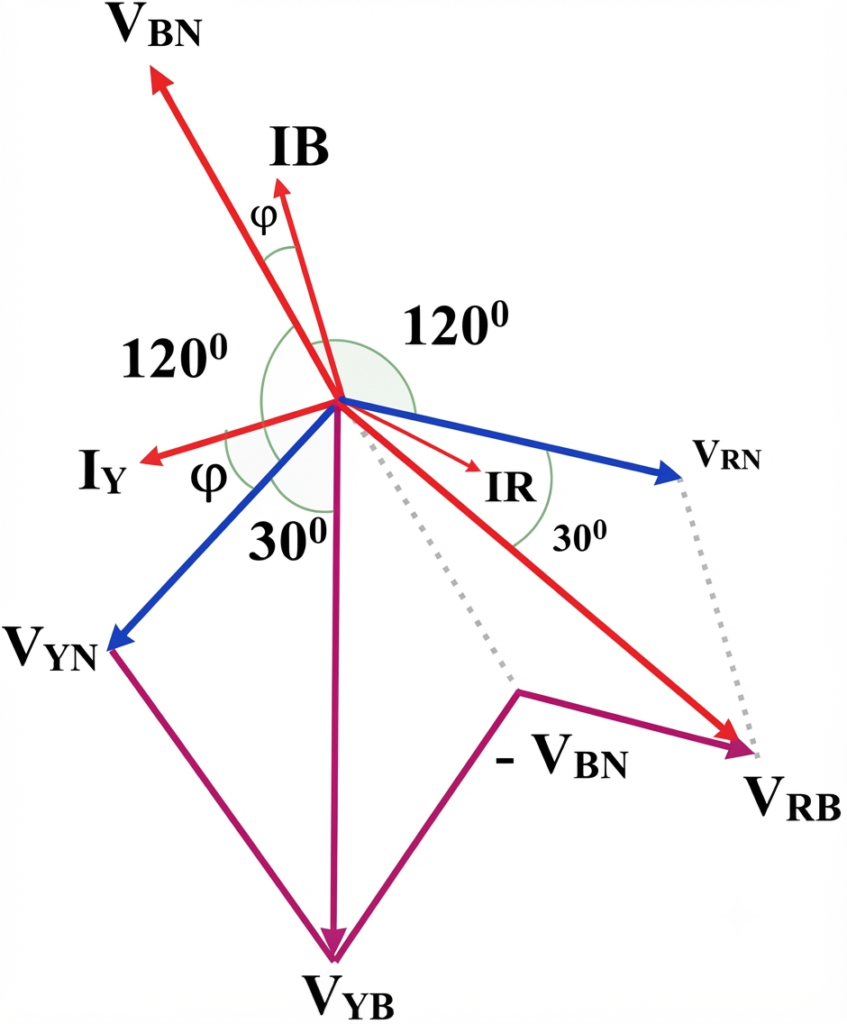
1. Derivation of Wattmeter Readings
For a balanced load, the phase voltages are separated by , and the line currents have the same phase relationships as their corresponding phase voltages, shifted by the load power-factor angle.
With the standard two-wattmeter connection, the first wattmeter measures:
The second wattmeter measures:
These expressions apply to a balanced load with the stated connection and a lagging power factor. For a leading load, the sign of the phase angle changes accordingly.
2. Total Active Power Derivation
The total active power is obtained by adding the two wattmeter readings:
Substituting the expressions for and :
Using the trigonometric identity:
We obtain:
This is the standard expression for the total active power of a balanced three-phase load.
The sum of the two wattmeter readings gives the total active power. This result also holds for unbalanced three-phase, three-wire loads, even though the individual balanced-load equations no longer apply.
Power Factor Calculation Using the Two Wattmeter Method
The power factor of a balanced three-phase load can be calculated using the two wattmeter readings.
From the earlier equations:
Subtracting the second reading from the first:
Using the identity:
We obtain:
The total active power is:
Dividing the difference by the sum gives:
Therefore:
The power factor is:
Alternatively, it can be written directly in terms of the wattmeter readings:
Important: This power-factor formula assumes a balanced load. For a leading load or a different wattmeter connection, the sign convention must be adjusted accordingly.
Reactive Power Calculation Using the Two Wattmeter Method
Reactive power represents the alternating exchange of energy between the source and reactive elements such as inductors and capacitors.
For a balanced three-phase load, the reactive power magnitude can be calculated from the difference between the two wattmeter readings.
From the derivation:
The total three-phase reactive power is:
Multiplying the wattmeter difference by gives:
Where:
- = Total reactive power in volt-amperes reactive (var)
- and = Signed wattmeter readings in watts
This expression gives the signed reactive power according to the stated connection and phase convention. For a balanced lagging load, is positive under this convention. For a leading load, the sign reverses.
The formula should not be applied directly to an unbalanced load as a general measurement of total reactive power.
Relationship Between Wattmeter Readings and Power Factor
The two wattmeter readings vary according to the load power factor.
| Load power factor | Phase angle | Wattmeter readings |
| Unity | 0° | Both readings are equal |
| 0.866 lagging | 30° | One reading is greater than the other |
| 0.5 lagging | 60° | One wattmeter reads zero |
| Below 0.5 lagging | Greater than 60° | One wattmeter reads negative |
| 0.5 leading | −60° | One wattmeter reads zero, with the roles reversed |
For a balanced load with a power factor below 0.5, one wattmeter indicates negative power. With an analog wattmeter, the pointer may attempt to move backward. The appropriate coil connections may be reversed to obtain an upscale indication, but the reading must then be treated as negative when calculating total power.
Observation Table for the Two Wattmeter Method
The following table can be used to record measurements during a laboratory experiment.
| S. No. | Line voltage (VL) (V) | Line current (IL) (A) | W1 (W) | W2 (W) | Total power (P = W1 + W2) (W) | Power factor |
| 1 | — | — | — | — | — | — |
| 2 | — | — | — | — | — | — |
| 3 | — | — | — | — | — | — |
Record the readings with their correct signs. For balanced loads, calculate the power factor using the derived equation and compare the measured total power with the theoretical value.
Advantages of the Two Wattmeter Method
The main advantages of this method are:
- Requires only two wattmeters: Total active power can be measured without using three separate wattmeters.
- Suitable for balanced and unbalanced loads: It measures total active power in three-phase, three-wire systems.
- No neutral connection required: The method works without connecting the wattmeters to the load neutral.
- Applicable to star and delta loads: The load connection does not need to be opened to insert a neutral connection for the measurement.
- Power factor calculation: For balanced loads, the readings can be used to determine the power factor.
- Reactive power calculation: The wattmeter difference provides reactive power for balanced loads under the specified connection convention.
Disadvantages of the Two Wattmeter Method
Despite its benefits, the method has some limitations.
- Negative readings at low power factors: For a balanced load with a power factor below 0.5, one wattmeter reads negative.
- Power-factor calculation requires a balanced load: The standard power-factor equation cannot be applied directly to a general unbalanced load.
- Reading errors: Analog instruments may introduce scale-reading and parallax errors.
- Connection errors: Incorrect current-coil or pressure-coil connections can lead to incorrect readings.
- Reactive power limitations: The standard reactive-power formula is valid for balanced loads and should not be treated as a general unbalanced-load formula.
Precautions When Using the Two Wattmeter Method
Follow these precautions to obtain reliable measurements.
- Check the current and voltage ratings of both wattmeters before making connections.
- Connect each current coil in series with its intended supply line.
- Connect the pressure coils across the correct line-to-line voltages.
- Tighten all terminals and verify the circuit before energizing the supply.
- Confirm the polarity and terminal markings of each wattmeter.
- If a wattmeter reads backward, follow the manufacturer’s procedure for reversing the appropriate coil connections and record the reading with the correct negative sign.
- Avoid touching exposed conductors while the circuit is energized.
- Use appropriate protective equipment and follow laboratory or site electrical safety procedures.
Applications of the Two Wattmeter Method
The two wattmeter method is used in a variety of electrical testing and measurement applications.
- Three-phase motor testing: Measuring the active input power of induction motors and other three-phase machines.
- Industrial power monitoring: Measuring total power consumption in three-phase, three-wire distribution systems.
- Electrical laboratories: Demonstrating three-phase power measurement and verifying power equations.
- Power-system testing: Checking the active power delivered to three-phase loads.
- Power-factor experiments: Calculating the power factor of balanced three-phase loads.
- Reactive power studies: Determining reactive power in balanced AC systems from the wattmeter readings.
Conclusion
The two wattmeter method is a practical and widely used technique for measuring total active power in three-phase, three-wire electrical systems. It uses two wattmeters connected to different supply lines, and the algebraic sum of their readings gives the total active power for both balanced and unbalanced loads.
For balanced loads, the difference between the readings can also be used to calculate the power factor and reactive power. Although one wattmeter may indicate a negative reading at low power factors, the method remains valuable for industrial measurements, motor testing, and electrical laboratory experiments.