An electrodynamometer type wattmeter is an electrical measuring instrument used to measure active power in AC and DC circuits. It operates on the interaction between the magnetic fields produced by its fixed current coils and moving pressure coil. Unlike induction-type instruments, it can measure power in both AC and DC circuits.
In an AC circuit, a wattmeter indicates real power, which depends on the applied voltage, load current, and power factor. This makes the electrodynamometer type wattmeter useful for laboratory measurements, electrical testing, and instrument calibration.
Construction of an Electrodynamometer Type Wattmeter
An electrodynamometer wattmeter consists of two coil systems, a moving mechanism, a control system, an air-friction damping arrangement, and a pointer with a calibrated scale.
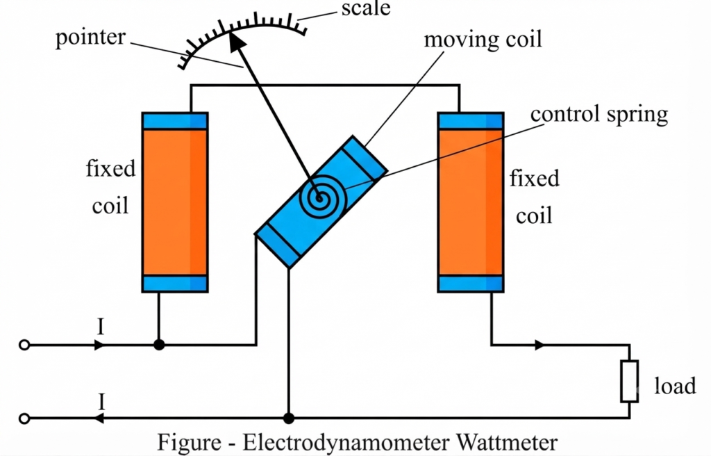
Its main components are described below.
1. Fixed Current Coils
The fixed coils are also called current coils or series coils. They are connected in series with the load so that the load current flows through them.
The current coils are generally divided into two sections. This arrangement produces a magnetic field around the moving coil while providing sufficient space for its movement.
Their main characteristics are:
- Made with conductors suitable for the rated load current.
- Designed with relatively few turns to limit resistance and power loss.
- Connected in series with the load.
- Responsible for producing the magnetic field associated with load current.
The current rating must match the selected instrument range. The wattmeter’s current and voltage ratings should always be checked before making a measurement.
2. Moving Pressure Coil
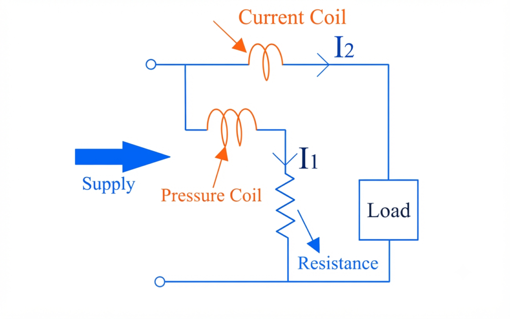
The moving coil, also known as the pressure coil or voltage coil, is connected across the measured voltage through a high-value series resistance.
It is mounted on a pivoted spindle or suspension and carries the pointer. When current flows through the moving coil, its magnetic field interacts with the field of the fixed coils, producing deflecting torque.
The pressure-coil circuit is designed to have a high resistance so that its current remains small. A low-inductance series resistor is commonly used to minimize the phase difference between the pressure-coil current and the applied voltage.
3. Control System
The control system provides the restoring torque required to establish a steady pointer position.
Two common methods of controlling pointer movement are:
- Spring control: Spiral springs provide restoring torque and may also carry current to the moving coil.
- Gravity control: A controlled gravitational force provides restoring torque.
Spring control is generally used in electrodynamometer wattmeters because the instrument can operate independently of its orientation, within its specified operating conditions.
4. Damping System
The damping system prevents excessive oscillation of the pointer and helps it settle at the correct reading.
Electrodynamometer wattmeters commonly use air-friction damping. Eddy-current damping is generally avoided because the additional magnetic field produced by eddy currents could affect the instrument’s operating torque.
5. Pointer and Scale
The pointer indicates the measured power on a calibrated scale. The scale can be designed to be approximately uniform over the instrument’s working range.
The pointer position depends on the average deflecting torque and the restoring torque provided by the control system.
Working Principle of an Electrodynamometer Type Wattmeter
The electrodynamometer wattmeter works on the principle that two current-carrying coils exert a mechanical force on each other because of their magnetic fields.
The fixed current coil carries load current, while the moving pressure coil carries a current proportional to the applied voltage. The interaction between their magnetic fields produces a torque that moves the pointer.
The working process is as follows:
- The fixed current coils are connected in series with the load.
- The moving pressure coil is connected across the supply through a high resistance.
- Load current produces a magnetic field in the fixed coils.
- The voltage-proportional current produces a magnetic field in the moving coil.
- The interaction between the two fields generates deflecting torque.
- The pointer moves until the average deflecting torque balances the controlling torque.
For an AC circuit, the average torque depends on the product of voltage and current and on the phase angle between them. Therefore, the wattmeter indicates active power when the pressure-coil current is sufficiently in phase with the applied voltage.
Torque Equation of an Electrodynamometer Type Wattmeter
The torque equation explains why the instrument measures electrical power.
Let:
- = instantaneous current through the fixed current coil
- = instantaneous current through the moving pressure coil
- = mutual inductance between the two coil systems
- = angular deflection of the moving system
- = instantaneous applied voltage
- = total resistance of the pressure-coil circuit
- = RMS supply voltage
- = RMS load current
- = phase angle between voltage and load current
- = spring constant
Step 1: Instantaneous Deflecting Torque
The instantaneous deflecting torque is proportional to the product of the two coil currents and the rate of change of mutual inductance with angular displacement.
Here, is the instantaneous deflecting torque.
Step 2: Pressure-Coil Current
Assuming that the pressure-coil circuit is predominantly resistive, its instantaneous current is approximately:
This assumption means that the pressure-coil current follows the applied voltage closely. In an actual instrument, a small phase-angle error may remain because of coil inductance and other circuit effects.
Step 3: Load Current and Voltage
For a sinusoidal AC supply, take the voltage as the reference:
The instantaneous current flowing through the pressure coil is given by:
If the load current lags the voltage by the phase angle , then:
For a leading load, the phase angle is negative under this convention.
Step 4: Substitute the Currents
Substituting the expressions for and into the torque equation gives:
The moving system responds to the average torque rather than following every instantaneous variation during an AC cycle.
Using the trigonometric identity for the product of two cosine functions, the average of the current product over one complete cycle is:
Therefore, the average deflecting torque is:
For a given instrument and operating range, the terms involving pressure-circuit resistance and the change in mutual inductance determine the instrument’s sensitivity.
Step 5: Controlling Torque and Final Equation
For spring control, the controlling torque is:
At the steady pointer position, the average deflecting torque equals the controlling torque:
Hence,
If the change in mutual inductance with deflection is approximately constant, the relationship becomes:
The active power in a single-phase sinusoidal AC circuit is:
Thus, the wattmeter’s deflection is proportional to active power under the stated assumptions.
For a DC circuit, the corresponding power relationship is:
Since the instrument’s operating torque depends on the interaction between the two coil currents, an appropriately designed and calibrated electrodynamometer wattmeter can measure power on both AC and DC supplies.
Advantages of an Electrodynamometer Type Wattmeter
The principal advantages are:
- AC and DC measurements: It can measure power in both types of circuits.
- Accurate power measurement: It can provide accurate results when properly calibrated and used within its specified operating range.
- Approximately uniform scale: The scale can be designed to provide convenient readings across the working range.
- No permanent magnet required: The operating magnetic field is produced by the current-carrying coils.
- Calibration applications: Its operating principle makes it suitable for laboratory measurements and calibration work.
Errors in an Electrodynamometer Type Wattmeter
Several factors can cause the indicated power to differ from the actual power.
1. Pressure-Coil Inductance
The pressure coil has some inductance. Consequently, its current may lag behind the applied voltage. This phase difference can introduce an error in the measured power, particularly at low power factors.
Reduction: Use a suitable low-inductance series resistor and operate within the instrument’s specified frequency range.
2. Pressure-Circuit Capacitance
Capacitance in the pressure circuit, including that associated with the resistor and wiring, can affect the circuit impedance and phase relationship. Its influence may become more significant at higher frequencies.
Reduction: Use the recommended circuit arrangement and avoid unnecessary wiring changes.
3. Mutual Inductance Between Unintended Circuits
Unwanted magnetic coupling between instrument circuits or nearby conductors can change the effective torque and produce measurement errors.
Reduction: Follow the manufacturer’s connection instructions and keep the instrument wiring properly arranged.
4. Connection Error
The way the wattmeter is connected determines whether the pressure-coil power consumption or the current-coil loss contributes to the reading. Depending on the connection, the indicated power may include a small additional component.
Reduction: Select the connection according to the expected load and required measurement accuracy.
5. Eddy Currents in Nearby Metal
Conductive materials near the instrument can develop eddy currents when exposed to changing magnetic fields. These currents produce secondary magnetic fields that may alter the operating torque.
Reduction: Keep the instrument away from unsuitable conductive structures and follow the recommended installation conditions.
6. Mechanical Friction and Vibration
Pivot friction, bearing wear, pointer oscillation, and external vibration can prevent the moving system from settling at the correct position.
Reduction: Place the instrument on a stable surface, check the mechanical condition, and allow the pointer to settle before recording the reading.
7. Temperature Changes
Changes in temperature affect the resistance of the current coil, pressure coil, and series resistor. These changes can alter circuit currents and the instrument’s calibration.
Reduction: Observe the specified operating temperature and allow the instrument to stabilize before precision measurements.
8. Stray Magnetic Fields
The operating magnetic field of an electrodynamometer instrument is relatively weak because it is produced by air-cored coils. External magnetic fields can therefore influence the torque.
Reduction: Keep the instrument away from strong external magnetic fields. Where applicable, use the manufacturer’s recommended shielding or compensating arrangement.
Advantages of Electrodynamometer Type Wattmeter
- AC and DC measurements: It can measure electrical power in both AC and DC circuits.
- Nearly uniform scale: The scale can be designed to provide approximately uniform readings over the specified operating range.
- High accuracy: Proper design, calibration, and operating conditions can provide accurate power measurements.
Disadvantages of Electrodynamometer Type Wattmeter
- Sensitivity to stray magnetic fields: External magnetic fields can affect the readings because the instrument produces a relatively weak operating field. Magnetic shielding, such as a suitable soft-iron enclosure, can help reduce this effect.
- Errors at low power factors: The inductance of the pressure coil can cause a phase-angle error, which may significantly affect measurements at low power factors.
Applications of an Electrodynamometer Type Wattmeter
Electrodynamometer wattmeters are used in several electrical measurement applications:
- Measuring active power in AC laboratory circuits.
- Measuring power in DC circuits.
- Testing electrical equipment during performance evaluation.
- Checking power consumption in electrical experiments.
- Calibrating other power-measuring instruments.
- Conducting electrical testing and verification within the instrument’s specified ratings.
Conclusion
An electrodynamometer type wattmeter measures active power through the interaction of magnetic fields produced by its fixed current coils and moving pressure coil. Its average deflecting torque depends on the voltage-current product and the phase relationship between them.
The torque equation establishes that the pointer deflection is proportional to (VI\cos\phi) for sinusoidal AC under the usual assumptions. Its ability to operate on both AC and DC, together with its suitability for precision laboratory measurements, makes it an important instrument in electrical engineering.
Read Next: