Discover the different types of transformers, including step-up, step-down, power, distribution, instrument, single-phase, and three-phase transformers. Learn about their functions, applications, and key differences in electrical systems.
Various types of transformers are used in electrical power systems for generation, transmission, distribution, and utilization of electrical energy. These transformers ensure efficient power transfer across different voltage levels, minimizing energy losses. Their design and application vary based on factors such as load requirements, efficiency, and the specific function they serve.
Step-up and step-down transformers are essential for voltage regulation in power systems. Step-up transformers increase voltage for long-distance transmission, reducing losses, while step-down transformers decrease voltage for safe distribution to consumers. Both types help maintain grid stability, ensuring electrical energy is transmitted efficiently from power plants to homes and industries.
Power and distribution transformers serve different purposes in electrical networks. Power transformers operate at high voltages in substations, handling large loads, whereas distribution transformers supply lower voltages to end-users. Instrument transformers, including current and potential transformers, provide accurate measurements and protection by isolating measuring instruments from high-voltage power lines.
Transformers can also be classified based on their configuration. Single-phase transformers are used in residential applications, while three-phase transformers are essential for industrial and commercial power distribution. Autotransformers, which have a single winding, offer improved efficiency in specific applications, such as railway systems and voltage regulation, by using common winding sections.
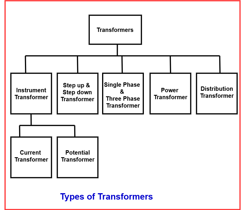
Types of Transformers
The different types of transformers illustrated in the below figure are explained in detailed.
Step up and Step down Transformer
Step-up and step-down transformers are classified based on the number of turns in their primary and secondary windings, which determine the induced electromotive force (emf). These transformers play a crucial role in voltage regulation within electrical power systems, ensuring efficient transmission and distribution of electrical energy across various applications.
A step-up transformer increases voltage while reducing current in an AC system. It has more turns in the secondary winding than in the primary winding. When the output voltage (V2) is greater than the input voltage (V1), the transformer raises the voltage level, making it suitable for long-distance power transmission.
A step-down transformer reduces voltage while increasing current. In this type, the primary winding has more turns than the secondary winding. When the output voltage (V2) is lower than the input voltage (V1), the transformer lowers the voltage level, making it ideal for supplying power to residential and industrial users.
Power Transformer
Power transformers are used in high-voltage transmission networks to facilitate efficient power distribution. Their voltage ratings typically include 400 KV, 200 KV, 110 KV, 66 KV, and 33 KV, with power capacities exceeding 200 MVA. These transformers are primarily installed at power generation stations and transmission substations, designed to operate at nearly 100% efficiency.
Since power cannot be directly distributed at extremely high voltages, step-down power transformers reduce voltage levels to suitable values for further transmission. These transformers are not fully loaded at all times. While core losses occur continuously throughout the day, copper losses vary depending on the load cycle of the distribution network.
When connected to transmission networks, power transformers experience minimal load fluctuations as they are not directly linked to consumer endpoints. However, if used in a distribution network, the load varies significantly, leading to frequent voltage fluctuations. This distinction determines their placement and operational efficiency.
Power transformers operate continuously at transmission substations, resulting in ongoing core and copper losses. They enhance cost-effectiveness by enabling power generation at lower voltage levels. Increasing the voltage level reduces current flow, minimizing I²R losses and improving voltage regulation, making them vital for efficient power transmission.
Power Transformer: Definition, Types, and Applications
Distribution Transformer
A distribution transformer is designed to step down voltage levels for safe and efficient power distribution at the consumer end. It operates at lower voltage ratings, typically 11 KV, 6.6 KV, 3.3 KV, 440 V, and 230 V, with power ratings below 200 MVA. These transformers are essential in electrical distribution networks, ensuring voltage transformation before power reaches homes, industries, and commercial establishments.
The primary winding of a distribution transformer is made of enamel-coated copper or aluminum wire, while the secondary winding, which handles high current at low voltage, is constructed using thick aluminum or copper ribbons. To enhance insulation, resin-impregnated paper and oil are used, preventing electrical faults and ensuring safety. Transformer oil plays a critical role by cooling the transformer, insulating the windings, and protecting internal components from moisture damage.
Distribution transformers are classified based on mounting location, type of insulation, and nature of supply. Those rated below 33 KV are commonly used in industrial applications, while transformers rated at 440 V and 220 V are widely used for domestic purposes. They are compact, easy to install, and operate with minimal magnetic losses. Unlike power transformers, they are not fully loaded at all times. Their efficiency varies depending on the load cycle, peaking during the day and reducing at night. This variation is measured as All Day Efficiency, which typically ranges between 60% and 70%.
Applications of Distribution Transformers
- Used in pumping stations where voltage levels are below 33 KV.
- Provide power supply for overhead railway lines electrified with AC.
- In urban areas, multiple houses are fed by a single-phase distribution transformer, while in rural areas, each house may require a dedicated transformer based on load demand.
- Multiple distribution transformers are used to support power requirements in industrial and commercial areas.
- Essential in wind farms, where they act as power collectors, transferring generated energy to distant substations for further distribution.
Instrument Transformer
An instrument transformer is a type of isolation transformer used to transform current and voltage levels in electrical systems. It plays a crucial role in safely isolating the secondary winding from the high voltage and high current of the primary side. This isolation protects measuring instruments, energy meters, and protective relays from damage while ensuring accurate readings.
Instrument transformers are classified into two main types: Current Transformer (CT) and Potential Transformer (PT). These transformers allow precise measurement and monitoring of electrical parameters in high-voltage networks. Below is a detailed explanation of each type.
Current Transformer (CT)
A current transformer (CT) is used for both measurement and protection in electrical systems. When the circuit current is too high to be directly applied to measuring instruments, a CT steps it down to a manageable level. This allows instruments like ammeters, voltmeters, wattmeters, or protective relays to function safely and accurately.
The primary winding of a CT is connected in series with the main supply, while the secondary side is connected to measuring devices. A CT maintains an accurate current ratio and phase relationship, ensuring precise readings. The current ratio is a critical factor; for example, a CT with a 2000:5 ratio means that when 2000A flows through the primary, the secondary outputs 5A.
A CT’s accuracy depends on various factors, including burden, load, temperature, phase change, rating, and saturation. The total primary current is the vector sum of the excitation current and the reversed secondary current multiplied by the turns ratio. The formula is: Ip=I0+Is /KT
Where:
- Ip = Primary current
- Is= Secondary current (reversed)
- I0= Excitation current
- KT= Turns ratio
Potential Transformer (PT)
A Potential Transformer (PT), also known as a Voltage Transformer (VT), is used to step down high voltages to a safe level for measurement and protection. The primary winding is connected across the high-voltage line, while measuring instruments like voltmeters, protective relays, and energy meters are connected to the secondary winding.
The primary function of a PT is to reduce voltage to a measurable and safe level. For safety reasons, the primary winding is grounded. For example, if a PT has a voltage ratio of 500:120, it means that when 500V is applied to the primary, the secondary outputs 120V.
There are different types of Potential Transformers, including:
- Electromagnetic PT (Wire-wound transformer)
- Capacitor Voltage Transformer (CVT) (Uses a capacitor voltage divider)
- Optical PT (Works based on the electrical properties of optical materials)
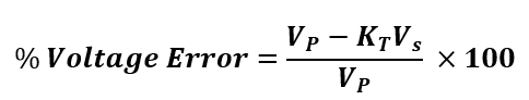
The percentage voltage error in a PT is calculated using a standard formula that determines accuracy in voltage transformation. The percentage voltage error can be calculated using the following equation.
Single-Phase Transformer
A single-phase transformer is a stationary electrical device that operates based on Faraday’s law of mutual induction. It efficiently transfers AC power from one circuit to another while maintaining a constant frequency and varying the voltage level. The transformer consists of two windings:
- Primary winding: Connected to the AC power supply.
- Secondary winding: Delivers power to the connected load.
The core of a single-phase transformer is typically made of laminated silicon steel to minimize eddy current losses. It is widely used in residential, commercial, and industrial applications for voltage regulation and power distribution. Depending on the number of turns in each winding, the transformer can either step up or step down the voltage.
Three-Phase Transformer
A three-phase transformer is formed when three single-phase transformers are interconnected, with their primary windings connected together and their secondary windings forming a single unit. This configuration enables it to function as a three-phase transformer, efficiently handling three-phase power systems.
Three-phase transformers play a vital role in electric power generation, transmission, and distribution, particularly in industrial applications. Instead of purchasing a single large three-phase transformer, assembling a bank of three single-phase transformers can be a more cost-effective solution.
The primary and secondary windings of a three-phase transformer can be configured in different ways:
| Primary Winding | Secondary Winding |
|---|---|
| Star (Wye) | Star (Wye) |
| Delta (Mesh) | Delta (Mesh) |
| Star (Wye) | Delta (Mesh) |
| Delta (Mesh) | Star (Wye) |
These configurations allow for different voltage transformations based on system requirements, improving efficiency and reliability in power distribution networks.
Conclusion
Transformers play a crucial role in electrical power systems, enabling efficient voltage regulation for generation, transmission, distribution, and utilization. Various types, including step-up, step-down, power, distribution, instrument, single-phase, and three-phase transformers, serve specific applications. Understanding their functions and differences helps in selecting the right transformer for efficient and safe power management.
Read Next: