Learn various methods of speed control of DC motor including flux control, armature control, voltage control, and modern techniques like thyristor-based systems. Understand principles, advantages, and applications with examples.
What is a DC Motor?
A DC motor (Direct Current motor) is an electrical device that converts electrical energy supplied by direct current (DC) into mechanical energy or rotational motion. It operates on the principle that a current-carrying conductor placed in a magnetic field experiences a force, which causes the motor’s shaft to rotate.
DC motors are widely used in many applications because of their simple design, reliable operation, and excellent control over speed and torque. They are commonly found in electric vehicles, industrial machines, robotics, household appliances like fans and mixers, and many other areas where precise speed control is needed.
This article explains the speed control of DC motor by various practical methods such as flux control, armature control, and voltage control. These techniques help adjust the motor speed for different industrial and domestic applications.
The key parts of a DC motor include the stator (which produces a magnetic field), the rotor or armature (which carries current and rotates), brushes, and a commutator that helps in reversing the current direction to keep the motor turning continuously.
Understanding the basic working of a DC motor helps us know why controlling its speed is important and how different methods can be applied to achieve efficient and smooth operation.
Why Speed Control is Necessary
In many industrial and domestic applications, the operating conditions of a DC motor can change depending on the load or task at hand. Speed control allows the motor to adjust its performance to meet these varying demands effectively.
Here are the key reasons why speed control is essential:
- Precision and Flexibility: Speed control ensures that the motor can operate at the desired speed required for specific tasks, improving process accuracy.
- Energy Efficiency: By adjusting the motor speed to the actual load requirements, power consumption is minimized, leading to energy savings.
- Extended Motor Life: Smooth and controlled operation reduces mechanical stress and wear, thus increasing the motor’s lifespan.
- Process Optimization: In applications like conveyors, fans, and machine tools, speed variation is critical for maintaining optimum performance and product quality.
Speed Equation of DC Motor
In a DC motor, the back EMF (Eb) is the electromotive force induced in the armature windings as a result of the armature rotating in the magnetic field. This induced EMF opposes the applied voltage and plays a crucial role in determining the motor’s speed.
The magnitude of the back EMF is given by the EMF equation of a DC generator:
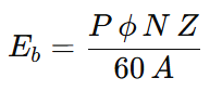
Where:
- P = Number of poles
- ϕ = Flux per pole (in Weber)
- N = Speed of the motor (in RPM)
- Z = Total number of armature conductors
- A = Number of parallel paths in the armature winding
Back EMF can also be expressed as:
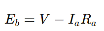
Where:
- V= Applied voltage
- Ia = Armature current
- Ra = Armature resistance
By substituting and rearranging, we get:
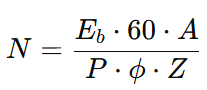
Since P, A, and Z are constants for a given motor, we can simplify:
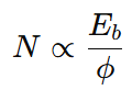
The above formula can be written as,
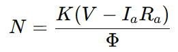
Explanation:
- From this equation, it is clear that speed is directly proportional to the applied voltage and inversely proportional to the flux.
- Any variation in the armature voltage V, armature resistance Ra, or magnetic flux Φ directly affects the motor speed.
- Therefore, by controlling these parameters, the speed of the DC motor can be effectively regulated.
Factors Affecting Speed
The following factors influence the speed of a DC motor:
- Armature Voltage (V): Increasing the voltage increases the speed proportionally, assuming flux remains constant.
- Armature Resistance (Rₐ): Higher resistance causes a greater voltage drop , reducing the effective voltage and thus speed.
- Armature Current (Iₐ): A higher current increases the voltage drop across the resistance.
- Magnetic Flux (Φ): Speed is inversely proportional to flux. A stronger field (higher flux) will lower the speed.
- Load Torque: As load increases, the motor tends to slow down slightly due to increased current draw and magnetic loading.
- Brush and Commutator Conditions: Poor contact or wear can increase electrical resistance, lowering speed.
Overview of Speed Control Methods of DC motor
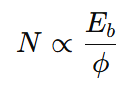
From the speed formula for a DC motor N∝Eb/ϕ, it is clear that the speed of a DC motor can be varied by changing either the back EMF Eb or the flux ϕ. Based on this principle, the three most common methods of speed control in DC motors are:
- Flux Control Method (varying ϕ)
- Armature Resistance Control Method (varying armature circuit resistance)
- Voltage Control Method (varying applied voltage V and thereby Eb)
Now, let’s explore how these three methods are practically applied in controlling the speed of DC Shunt Motors and DC Series Motors.
Speed control Methods for DC Shunt motor
1. Flux Control Method
As explained earlier, the speed of a DC motor is inversely proportional to the flux per pole (ϕ). Therefore, reducing the flux increases the motor speed, and increasing the flux decreases it.
To control the flux, a rheostat (variable resistor) is connected in series with the field winding, as shown in the circuit diagram. By increasing the resistance in the field circuit, the field current decreases, which in turn reduces the flux. As a result, the motor speed increases.

This method is particularly effective in DC shunt motors, where the field current is relatively low. Consequently, the power loss (I²R) in the rheostat is minimal, making this method quite efficient compared to others.
Although this approach can raise the motor speed above its rated value, it has limitations. Excessive weakening of the field can lead to poor commutation and spark generation at the brushes, potentially damaging the motor. Therefore, there is a practical limit to how much the speed can be increased using this method.
One of the main advantages of this method is that it is simple to implement. The setup does not require complex components, making it cost-effective and easy to maintain. Additionally, it offers a wide range of speed control, which is particularly useful in applications where variable motor speed is essential.
However, this method also has certain drawbacks. At higher speeds, there is often a reduction in torque, which may not be suitable for load-intensive operations. Furthermore, weakening the field to achieve higher speeds can sometimes result in motor instability, affecting performance and reliability.
2. Armature Control Method
The Armature Control Method is a widely used technique for adjusting the speed of a DC shunt motor, especially when speeds below the rated speed are desired.
The speed of a DC motor is directly proportional to the back EMF (Eb), and the back EMF is given by:

Where:
- V = Supply voltage
- Ia = Armature current
- Ra = Armature resistance
When both the supply voltage V and the internal armature resistance Ra remain constant, the back EMF Eb becomes directly dependent on the armature current Ia. Since motor speed is proportional to Eb, any decrease in Ia leads to a decrease in speed.
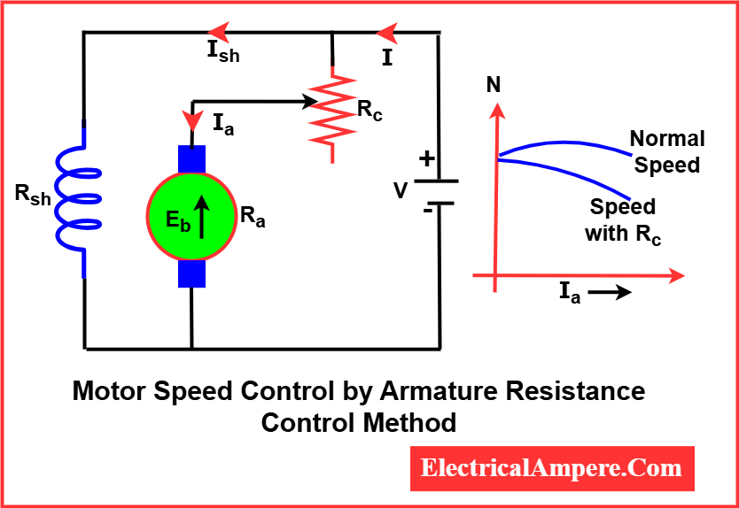
In this method of speed control of DC motor, a variable resistor (or controller resistance) is connected in series with the armature. As this resistance is increased:
- The total voltage drop across the series resistance increases.
- The voltage across the armature decreases.
- This reduces the armature current and, consequently, the motor speed decreases.
The more resistance added, the greater the drop in speed. However, this method is generally inefficient, as significant power is lost in the external resistor due to Ia2R losses. Despite this, it remains a simple and cost-effective method for applications requiring variable speed below the rated level.
3. Voltage Control Method
a). Multiple Voltage Control Method
In the Multiple Voltage Control method, the shunt field winding is connected to a fixed supply voltage, ensuring a constant field flux. The armature, however, is supplied with different voltage levels, which are selected using appropriate switchgear or tap-changing mechanisms.
Since the speed of a DC motor is directly proportional to the voltage across the armature (when flux is constant), varying the armature voltage results in a corresponding change in motor speed.

By switching between different pre-set voltage levels, discrete speed levels can be achieved. This method is simple, reliable, and provides good speed regulation, but is limited to applications where multiple fixed voltage sources or taps are available.
b). Ward-Leonard System
The Ward-Leonard system is employed when very precise and smooth speed control of a DC motor is required, such as in electric excavators, elevators, and cranes.
System Arrangement:
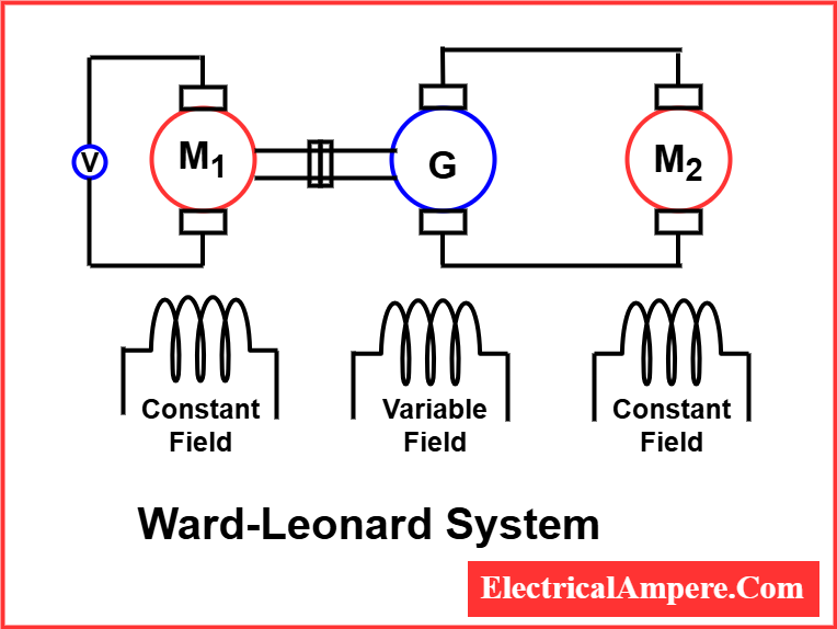
- M1: A prime mover, which can be either an AC motor or a DC motor running at a constant speed.
- G: A DC generator directly coupled to M1.
- M2: The DC motor whose speed is to be controlled.
In this system, the output voltage of the generator (G) is supplied to the armature of the motor (M2). By adjusting the field current of the generator G using a field regulator, the generator’s output voltage can be smoothly varied from zero up to its rated maximum. This variation directly changes the armature voltage of motor M2, allowing for very fine and continuous control of the motor’s speed over a wide range.
This method provides excellent speed regulation and control, making it ideal for applications demanding precise speed variation.
c). DC Drive Method of Speed Control
Modern DC drives use power electronic converters to control the speed of DC motors by adjusting the armature voltage smoothly and efficiently.
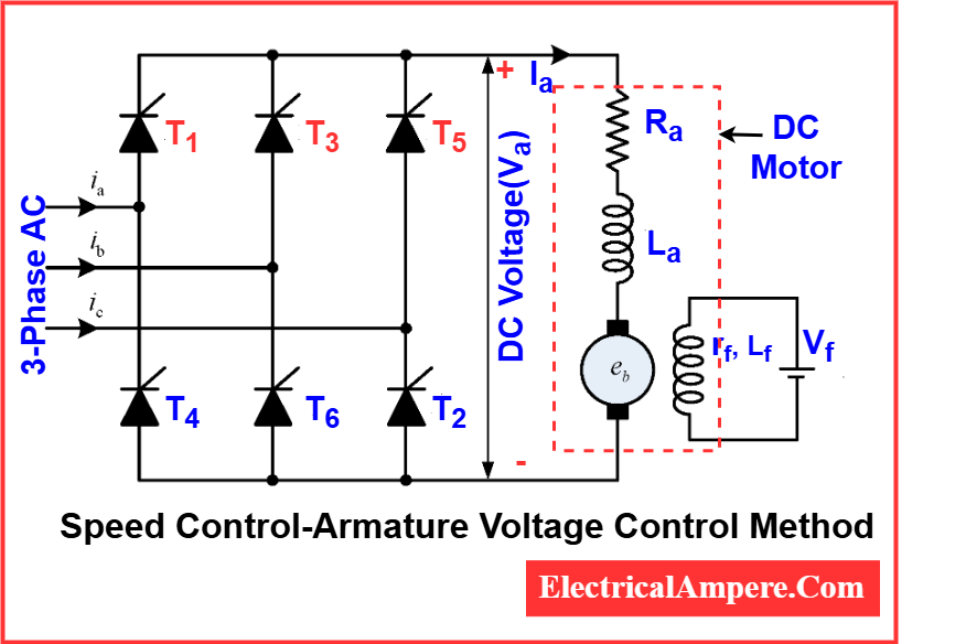
In these systems, a phase-controlled rectifier (using thyristors) converts AC supply to a variable DC voltage that is fed to the motor armature. The field is often supplied by a separate constant DC source. By controlling the firing angle of thyristors, the average output voltage can be regulated, thereby controlling the motor speed.
The DC drive method of speed control offers several advantages, making it a preferred choice in modern industrial applications. It provides high efficiency, ensuring minimal power loss during operation. The system allows for a smooth and wide range of speed control, making it suitable for processes that require fine adjustments. Additionally, DC drives offer a fast response to speed changes and come in compact designs, which is beneficial where space is a constraint. These drives are also highly suitable for automation and closed-loop control systems, enabling precise and consistent performance.
Due to these benefits, DC drives are commonly used in paper mills, rolling mills, traction systems, robotics, and CNC machines. Their precision, reliability, and ability to integrate seamlessly with modern control systems make them an essential part of many industrial setups.
Speed Control Methods of DC Series Motor
1. Flux Control Method
a). Field Diverter
A variable resistance, called a diverter, is connected in parallel with the series field winding as shown in Figure (a).
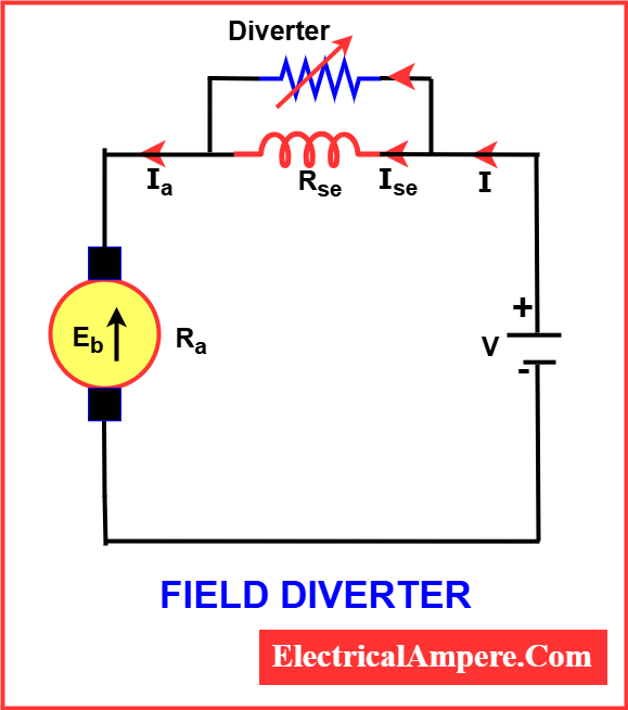
By adjusting this resistance, a desired portion of the current is diverted through the resistor, reducing the current flowing through the field coil. This decreases the magnetic flux (Φ), allowing the motor speed to increase.
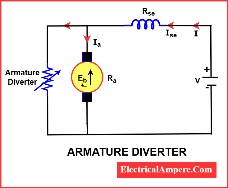
b). Armature Diverter
In this method, the diverter is connected across the armature as shown in Figure below.
.
For a constant load torque, if the armature current (Ia) is reduced, the flux (Φ) must increase to maintain torque because Ta∝ΦIaT_a \propto \Phi I_aTa∝ΦIa. This causes the motor to draw more current from the supply, increasing flux and consequently reducing the motor speed.
c). Tapped Field Control
As illustrated in below diagram, the field coil is divided into sections using taps.
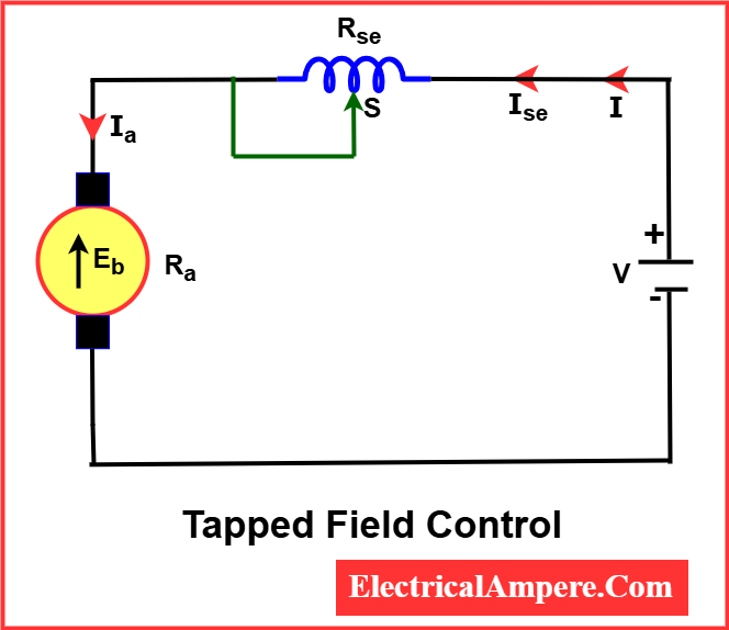
By selecting different taps, the number of turns in the field winding—and thus the flux (Φ)—can be adjusted, enabling different speeds.
d).Paralleling Field Coils
This method obtains multiple speeds by rearranging the connections of several field coils in parallel or series combinations. Changing these connections varies the total flux, thus controlling the motor speed.
e). Series-Parallel Control
This method is widely adopted in electric traction systems, especially where two or more mechanically coupled DC series motors are used (e.g., in trains or trams).
- At low speeds, the motors are connected in series. In this configuration, the same current flows through each motor, but the supply voltage is divided between them.
- At higher speeds, the motors are reconfigured in parallel. Now, the full supply voltage is applied across each motor, while the current gets divided among them.
This technique allows for efficient multi-speed control and smooth acceleration, making it ideal for traction applications where torque and speed need to be dynamically adjusted.
2. Variable Resistance in Series with Armature
In this method, a variable resistance is connected in series with the armature circuit.
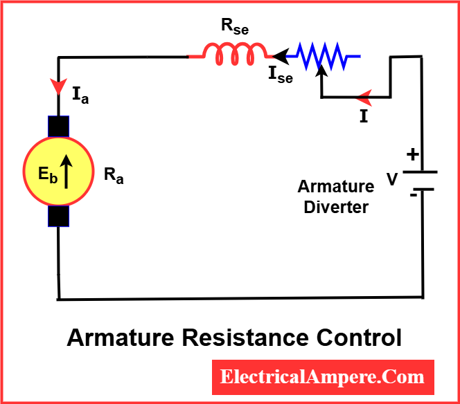
By increasing the series resistance, the voltage drop across the armature decreases, thereby reducing the back EMF. As a result, the speed of the motor decreases proportionally.
This technique is simple and cost-effective but comes with reduced efficiency due to energy losses in the resistor and is typically used for temporary or low-speed operations.
Comparison of Speed Control Methods for DC Motors
| Method | Applicable Motor | Speed Regulation | Efficiency | Complexity |
|---|---|---|---|---|
| Flux Control | Shunt, Series | Good | High | Low |
| Armature Control | Shunt | Very Good | High | Low |
| Voltage Control | Shunt | Good | Moderate | Moderate |
| Series-Parallel | Series | Good | Moderate | High |
Numerical Examples
- A 230 V DC shunt motor has a back EMF of 220 V at rated load. If the flux is reduced by 10%, what will be the new speed?
Given data:
- Rated voltage V=230 V
- Rated back EMF Eb1=220 V
- New flux ϕ2=0.9ϕ1 (10% reduction)
- Speed at rated load = N1
- New speed N2=?
Speed relation:
Assuming back EMF roughly constant,
New speed increases by 11%, so
If N1=1000 RPM, then
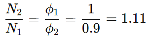
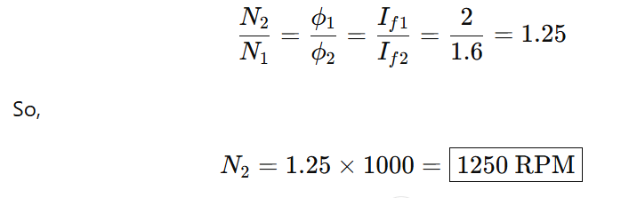
2. A 220 V DC shunt motor runs at 1000 RPM when the field current is 2 A. If the field current is reduced to 1.6 A, calculate the new speed, assuming load torque remains constant and armature resistance is negligible.
Solution:
Given:
- Initial voltage, V=220 V
- Initial speed, N1=1000 RPM
- Initial field current, If1=2
- New field current, If2=1.6
Assuming:
- Constant armature voltage (i.e., V is constant)
- Negligible armature resistance
- Torque is constant → Ia constant
- N∝1/ϕ
Now,
3. A 220 V DC shunt motor runs at 1000 RPM with a back EMF of 210 V. If an external resistance is added in the armature circuit, causing the back EMF to drop to 190 V, calculate the new speed. Assume the flux remains constant.
Solution:
Given:
- V=220 V
- Initial speed, N1=1000 RPM
- Initial back EMF, Eb1=210
- New back EMF, Eb2=190
- Flux is constant ⇒ N∝Eb
So,
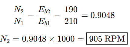
New speed = 905 RPM after adding resistance in the armature circuit.
Conclusion
Speed control of DC motors is essential for optimizing performance in various industrial and commercial applications. Each method of speed control—whether through flux control, armature resistance, voltage variation, or series-parallel configurations—offers distinct advantages depending on the motor type and application needs.
Flux and voltage control are commonly used for shunt motors, providing good speed regulation and efficiency. Armature control, while simple and cost-effective, is best suited for applications where slight efficiency losses are acceptable. For series motors, methods like field diverters and series-parallel control are effective in traction and variable-speed applications. Ultimately, the selection of a speed control method depends on the desired speed range, load characteristics, efficiency requirements, and system complexity.
FAQs-Basic Conceptual Questions
1. What is the relation between speed, back EMF, and flux in a DC motor?
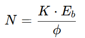
The speed of a DC motor is given by the formula:
Where:
- N = speed of the motor
- Eb = back EMF
- ϕ = flux per pole
- K = machine constant
Thus, speed is directly proportional to back EMF and inversely proportional to flux.
2. Why is speed control necessary in a DC motor?
Speed control is necessary to:
- Meet the varying load requirements of different applications
- Enhance process control in automation and manufacturing
- Improve efficiency and performance of machines
- Enable soft start and stop
- Provide speed variation in transport systems, tools, elevators, etc.
3. State the different methods of speed control for a DC shunt motor.
Common methods include:
- Flux Control Method – Changing field current to vary flux.
- Armature Resistance Control – Adding external resistance in the armature circuit.
- Voltage Control Method – Using variable voltage supply (e.g., Ward-Leonard system).
4. What is the function of a field diverter in a DC series motor?
A field diverter is a variable resistor connected in parallel with the field winding.
Its function is to divert part of the armature current away from the field, thereby reducing the field flux. As a result, the motor speed increases due to the inverse relationship between speed and flux.
5. What is the basic principle of the armature control method?
In the armature control method, additional resistance is inserted in series with the armature. This reduces the voltage across the armature, lowering the back EMF and consequently the speed.
This method is mostly used for speed reduction below the rated speed and is inefficient due to power losses in the added resistance.
Read Next:
- Regenerative Braking in DC Motor
- Speed Regulation of DC Motor
- Electric Motor
- Armature Reaction in DC Machine