An induction motor’s power flow diagram and loss analysis show how electrical power is converted into mechanical power, and the losses occur at various stages during power conversion.
Energy Conversion Process in Induction Motor
The stator of an induction motor receives a single-phase or three-phase AC supply, depending on the type of motor. The motor produces the magnetic flux in the core that links to the rotor and causes the rotor current to flow. The interaction of this rotor current and magnetic flux produces the torque that rotates the motor.
Thus, electrical energy is first converted into magnetic energy, and the magnetic energy is converted into electrical energy in the rotor circuit. Finally, the rotating torque produces mechanical energy. This way, electrical energy gets converted into mechanical energy in the motor.
The various losses occur in induction motors during the energy conversion process, and the major losses are fixed losses and variable losses.
We will first discuss on the types of losses and how these losses occur in induction motor.
Types of Losses in Induction Motor
Fixed Losses (No-Load Losses)
Eddy Current Loss: Some parts of the magnetic flux that travel through the core lekas from its path and induce voltage in the core, leading to setting up eddy current in a closed loop. The eddy current causes heat loss in the core is called the eddy current loss.
Hysteresis Loss: Also, the magnetic flux reversal causes hysteresis lag, leading to hysteresis loss in the motor. The eddy current and hysteresis losses are called no-load losses, and these losses depend on the voltage and frequency. The loading on the motor does not affect no-load losses. Therefore, it is called fixed or constant loss.
Friction Loss: As you know, a rotating machine creates friction in its bearing. The friction is created between the fixed and rotating parts of a motor. Thus, friction loss is another type of fixed loss.
Windage Loss: In a power flow diagram, a windage loss is also a part of fixed loss. When the motor rotates, it cuts the surrounding air, and the power lost in overcoming the air friction causes windage loss in an induction motor.
Variable Losses (Copper Losses)
Variable losses or copper losses depend on the loading of the motor. The higher the loading on the motor, the higher the variable or copper losses. The copper loss is the heat loss(I2R Loss) caused by the flow of electric current in the motor winding.
The motor winding is made of coils that have inductance and resistance. Though the resistance of the winding is very low, it causes heat loss in the motor when current flows through it.
The heat loss or copper loss depends on the current and the resistance of the winding, and it is proportional to the square of the current and resistance of the winding. The motor has two sets of winding: stator winding and rotor winding. The copper losses in the winding are,
- Stator Copper loss
- Rotor Copper loss
The copper loss in the induction motor can be calculated using the formula below.
Stator Copper Loss (Ps) = 3 × I12 × R1
Where, I1 is stator current and R1 is stator resistance
Induction Motor Power Flow Diagram
The power flow diagram of the induction motor is shown in the image below.
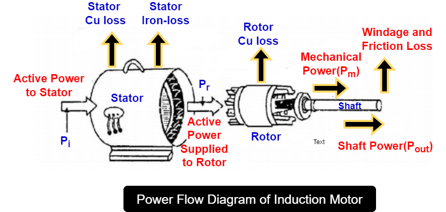
The output power of an induction motor can not be equal to the input power, or in other words, the motor efficiency can not be 100 %. Some parts of input power are lost in losses as heat energy, and output power is always less than the input power.
Stages of Power in an Induction Motor
Now, we will discuss the power stages of the motor to understand the various losses that take place in the different parts of an induction motor.
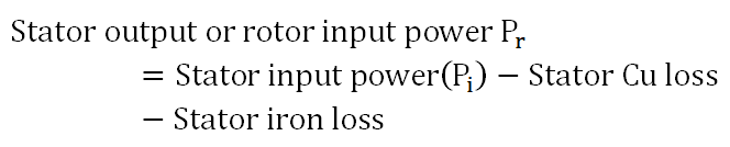
Rotor Input Power
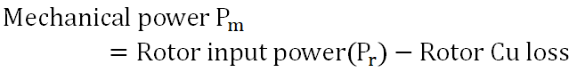
Mechanical Power
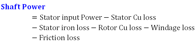
Shaft Power

Considering the above power terms, we can derive the power equation of an induction motor.
Power Equation of Induction Motor
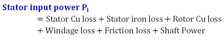
Stator Input Power Formula
or,
Power Flow Diagram of 3-Phase Induction Motor (Electrical Quantities)
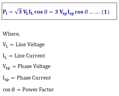
The input power drawn by the induction motor is;
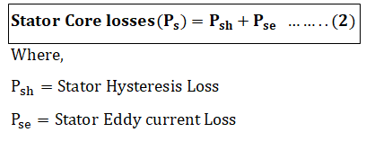
The stator core losses,-eddy, and hysteresis losses-contribute to no-load losses.
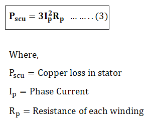
The copper loss in all three winding of the stator is given by stator copper loss formula:
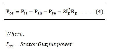
The output power of the stator is equal to The difference between the input power and losses is equal to the stator output. The stator output power is;
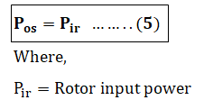
The rotor input is equal to the stator output power,
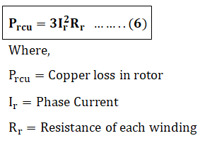
We can neglect the iron loss and hysteresis losses in the rotor because it is negligible because of lower voltage and frequency. The major loss that occurs in the rotor is copper loss, and it is mathematically expressed by the following equation.
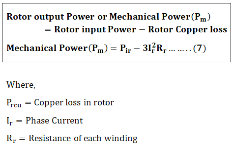
The difference between the rotor input power and losses is equal to the rotor output power.
The rotor output power or mechanical power(Pm) is expressed as ;
The difference between mechanical power and friction and windage loss is equal to the shaft power of an induction motor.
Conclusion
The Power Flow Diagram of a 3-Phase Induction Motor clearly shows how electrical energy is converted into mechanical energy. Understanding the fixed and variable losses in the stator and rotor, along with the stages of power from input to shaft output, helps in analyzing motor performance and efficiency.
By studying these diagrams and formulas, you can better grasp energy conversion and the factors affecting the operation of three-phase induction motors.
Read Next: