The pin type insulator is used for power distribution for voltages up to 33kV. It is mounted on the cross arm of a supporting tower. The pin insulator has grooves on the upper end to keep the conductor in place. The conductor is tied to the insulator on the top groove for straight line positions and on the side groove for angle positions with an annealed binding wire made of the same material as the conductor. The insulator body has a lead thimble that is cemented to receive the pin.
Materials Used in Pin Insulator
The pin insulator comprises non-conductive materials such as porcelain, ceramic, silicon rubber, or polymer. Polymer pin insulators are heavier compared to porcelain insulators.
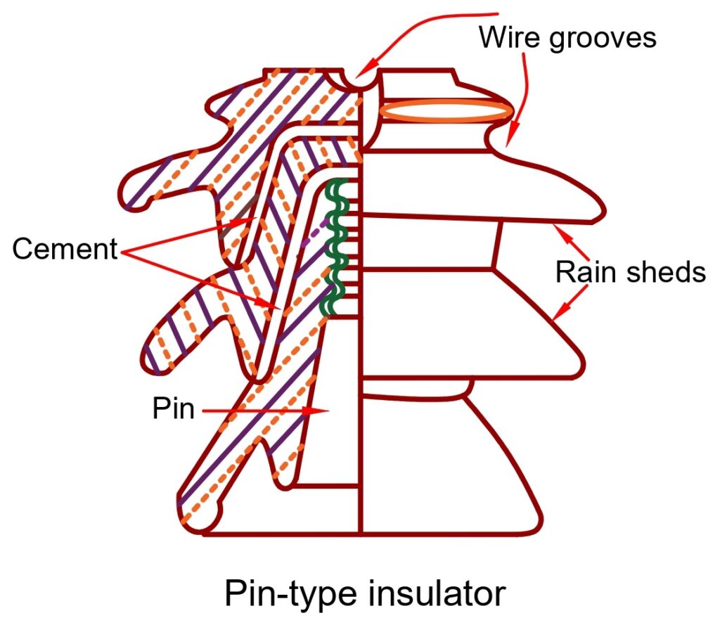
Pin Type Insulator Diagram
The diagram of the pin type insulator is illustrated in the image below, showing its key components such as the insulator body, grooves, rain sheds, and mounting pin.

Construction of Pin Type Insulator
A single-piece pin insulator is used for low voltage, and for high voltage, two or more pieces are cemented together to maintain the proper thickness. The petticoats or rain sheds of the insulator provides an adequate path for leakage current.
The top of the insulator has grooves designed to hold the conductor securely, whether for straight line or angled positions. A lead thimble is embedded in the body to receive the pin, which is mounted on the cross arm of the supporting tower.
Pin Insulator Voltage Rating (Used up to 33kV)
A pin insulator is generally used for distribution lines where the operating voltage is up to 33 kV. For low-voltage lines (below 11 kV), a single-piece pin insulator is sufficient. However, as the voltage level increases, the risk of flashover and puncture also increases. To withstand this, two or more insulator units are cemented together to provide the required thickness and creepage distance.
Beyond 33 kV, pin insulators become bulky, heavy, and uneconomical. For higher voltages (66 kV and above), suspension insulators are preferred instead, as they are lighter, more flexible, and can handle the mechanical stress better.
Thus, the voltage rating of pin insulators is limited to 33 kV, making them highly reliable for medium-voltage distribution systems but unsuitable for extra high voltage transmission.
Flashover and Arcing Distance in Pin Insulator
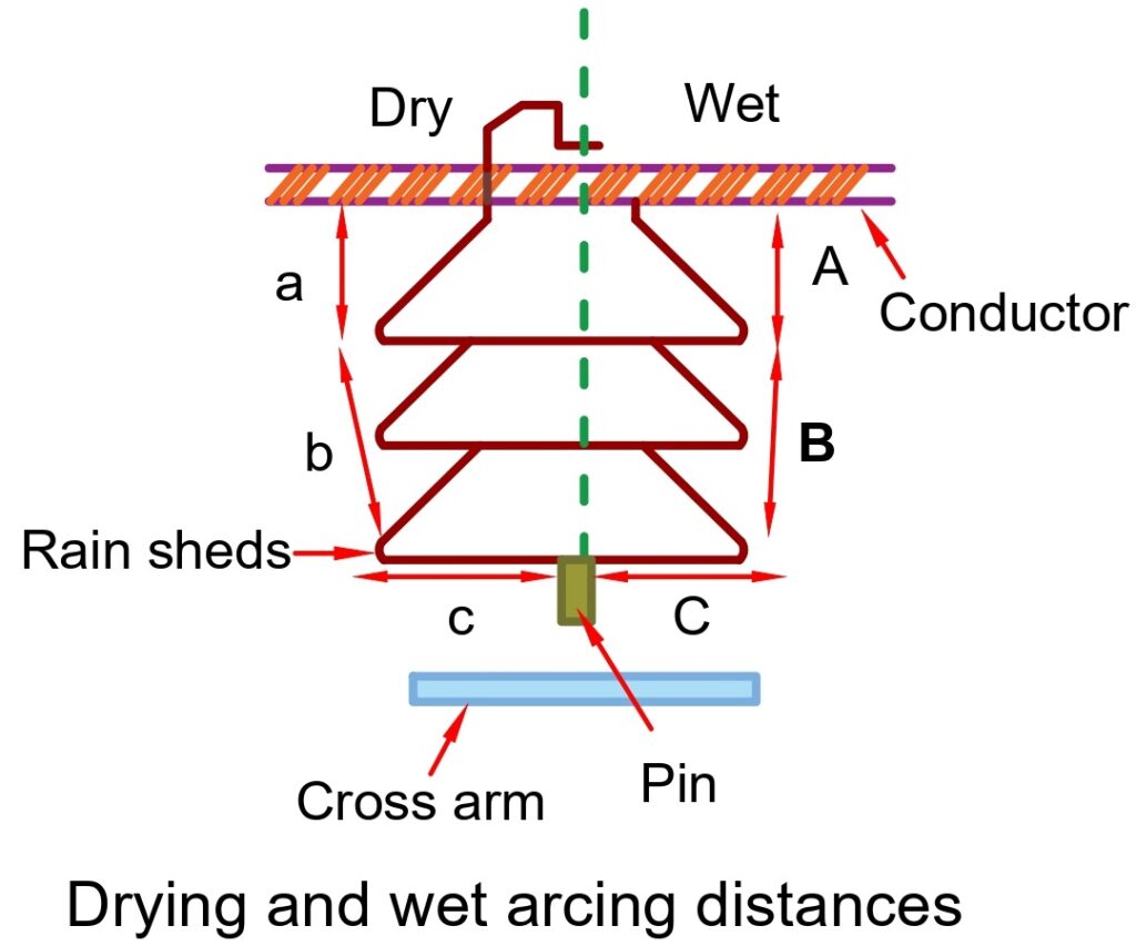
It is important to note that the flashover voltage for moist and dirty surfaces is lower than that for clean and dry surfaces. The total arcing distance through dry air is calculated by adding all the direct distances together, which is represented by (a+b+c). On the other hand, the total arcing distance through wet conditions is calculated by adding (A+B+C).

Advantages & Disadvantages of Pin Insulators
Advantages
- The material possesses a high level of mechanical strength.
- It has a reasonable creepage distance.
- The high-voltage distribution line utilizes it.
- The pin-type insulators are easy to construct and requires minimal maintenance.
- It can be used both vertically and horizontally.
Disadvantages
- It should be used together with the spindle.
- It is only suitable for the distribution line.
- The maximum voltage rating available is limited to 36kV.
- The pin used on the insulator can cause damage to the thread of the insulator.
Causes of Pin Type Insulator Failure
Insulator failure can occur due to either puncture or flashover. In case of a puncture, the electric current passes through the insulator’s body. On the other hand, flashover is caused by arc discharge between the conductor and the earth through the air surrounding the insulator.
The flashover occurs due to a line surge or wet conducting layer over the insulator’s surface. The insulator remains undamaged by the flashover, but it loses its functionality upon puncture.
The insulator is made with enough thickness to prevent punctures during surge conditions. To reduce flashovers, the resistance to leakage currents is increased. Petticoats or rain sheds are used to construct multiple layers, which make the leakage path longer. The rain sheds keep the inner surface dry during wet weather, providing enough leakage resistance to prevent flashovers.
Pin Insulator vs Suspension Insulator
Pin insulators are widely used in distribution lines up to 33 kV, and in some cases up to 66 kV. They are simple in design, easy to install, and provide strong mechanical support. However, at higher voltages, pin insulators become bulky, heavy, and expensive.
On the other hand, suspension insulators are better suited for 66 kV and above. They are made up of multiple disc insulators connected in series, which makes them flexible and adaptable for different voltage levels. If one disc fails, the rest can still function, ensuring reliability. Suspension insulators are also lighter compared to large pin insulators and can handle both mechanical stress and high electrical stress more effectively.
Conclusion
In conclusion, a pin insulator is a fundamental component in electrical distribution systems. It provides crucial insulation and support to overhead power lines.
For a complete overview, check out our Types of Insulators in Transmission Line guide.
Related Articles: