The HVDC circuit breaker serves as a switch to interrupt the flow of abnormal direct current in a circuit. In case of a fault in the system, the mechanical contacts of the circuit breaker are separated, thus breaking the circuit.
The High Voltage Direct Current (HVDC) system is a highly efficient method for transmitting power over long distances and is commonly used in green energy production. Multiple protection devices are used to safeguard costly equipment that is connected to these high-voltage transmission lines. One of these devices is the circuit breaker. Since DC operates differently than AC, the same circuit breaker designed for AC cannot be used. Attempting to use an AC circuit breaker can cause harm to the system. Therefore, HVDC circuit breakers are essential in such types of applications.
Circuit Breaker
A circuit breaker is a type of mechanical switch that functions automatically to safeguard a circuit from damage that may be caused by a fault current. It works by breaking the circuit upon sensing a huge draw of current flow caused by overloading or short circuits. It can also be manually opened to enable maintenance or fault clearance. It is designed to safely close and open a circuit, protecting it from damage.
The primary purpose of a circuit breaker is to safely interrupt the flow of electricity in a circuit.
- It should be able to withstand the fault current for a short period of time.
- It should safely break the closed electrical circuit.
- It should extinguish the arc quickly.
- The terminals must be able to endure the voltage even after they have been disconnected.
- It should prevent the formation of a new electric arc after the initial one has been extinguished.
The circuit breaker detects the high fault current using various mechanisms. These are-
- Heating effect
- Electromagnetic effect
- Current sensors using CTs
The circuit breaker momentarily withstands the fault current and allows other circuit breakers to resolve the fault. It is designed to tolerate a specific range of fault currents without damaging its terminals.
After detecting a fault current, the circuit breaker trips and interrupts the current flow. It achieves this by breaking the circuit through the use of stored mechanical energy, such as a spring or a blast of compressed air, to separate the contacts. Alternatively, the fault current can be utilized to break open the contacts, either through thermal expansion or an electromagnetic field using a solenoid.
After the contacts are separated, the next step is to extinguish the arc. This arc is created between the contacts due to high voltage. If left unchecked, it can generate excessive heat, which may damage the CB contacts or terminals due to high currents.
The electrical arc attempts to complete the circuit, allowing the current to flow. It must be extinguished, and various types of circuit breakers use different insulating or dielectric arc extinction mediums.
- Air
- Vacuum
- Insulating Oil
- Insulating gas such as SF6 (Sulphur hexafluoride)
Various techniques are used to quickly and safely extinguish an arc aside from arch quenching.
In air blast circuit breakers, a blast of compressed air is used to quench the arc. This process replaces ionized air particles with non-ionized air molecules that have a higher dielectric strength. This increase in resistance reduces the current, which leads to the extinction of the arc.
- Cooling of Arc: When an electrical arc occurs, it heats up the air molecules, which causes them to ionize. This, in turn, reduces the resistance of the air. To stop the arc, it is important to cool it down. Cooling the arc will help the ionized particles to recombine into their natural state which increases the dielectric strength of the air molecule. This process increases the resistance of the medium, which results in the voltage required to maintain the arc also increasing. As a result, the current flowing through the arc starts to drop, ultimately resulting in the arc being extinguished.
- Air Blasting: In air blast circuit breakers, a blast of compressed air is used to quench the arc. This process replaces ionized air particles with non-ionized air molecules that have a higher dielectric strength. This increase in resistance reduces the current, which leads to the extinction of the arc.
- Increasing the length of the arc: The voltage required to maintain an arc is directly proportional to its length. Increasing the distance between the contact terminals will cause the arc to extinguish.
- Reducing the cross-section of the arc: One technique to extinguish an arc is to reduce its cross-section by minimizing the contact sizes. This increases the voltage required for the arc to continue and eventually extinguishes it.
- Deflecting the arc: In this technique, a magnetic field is produced to deflect the arc. The blowing arc into a section of the circuit breaker occurs in the arc chute. The air chute cools off & extinguishes the arc.
- Dividing or splitting the arc: The technique involves splitting an arc into multiple smaller arcs by creating several contacts in between. This is done by splitting the arc into several small arcs in series, which increases its length and resistance. As a result, the arc current decreases gradually until it eventually becomes zero.
- Zero current quenching: The most common method used in AC circuit breakers involves opening the circuit at the exact point of zero current. This is because there are multiple points of zero current in an AC waveform, and opening the circuit at these points prevents the current from rising and generating an
- Using charged capacitors in parallel: This technique is used in DC circuit breakers. The DC circuit does not have a natural zero current, so a charged capacitor with an inductor is used in parallel to introduce an artificial zero current in the line, which extinguishes the arc.
Comparison of AC Circuit Breaker & DC Circuit Breaker
As explained earlier, AC current fluctuates along the zero line, creating numerous natural zero crossings approximately 100 times per second at 50 Hz. This is why AC circuit breakers exploit this characteristic of AC to extinguish the arc when the current is at the zero point.
DC circuit breakers are more complex in design compared to AC circuit breakers. This is because they require additional circuitry to introduce artificial zero currents in the line to extinguish the arc.
HVDC Circuit Breaker
A High Voltage Direct Current (HVDC) circuit breaker is a specialized device designed to protect HVDC circuits against fault current.
As we previously discussed, the primary feature that distinguishes the DC circuit breaker from other types of breakers is its arc quenching technique. In AC breakers, breaking the circuit at zero crossing is easier because the energy at that point is zero, thus preventing the generation of an arc at that voltage level. However, in DC circuits, the voltage and current never reach zero. As a result, there is always a very high voltage and current between the contacts during separation.
Requirement for HVDC Circuit Breaker
The operation and design of HVDC circuit breakers are more complex than AC circuit breakers due to the absence of natural zero crossing. In HVDC, the generated arc will not extinguish and will heat the contacts of the breaker. This can ultimately lead to the destruction of the contacts, making the entire circuit breaker useless.
Furthermore, the connected equipment can be damaged from the fault current because the circuit remains complete. To ensure safe circuit breaking in the HVDC circuit breaker, the following requirements must be fulfilled.
- Creation of an artificial zero-crossing
- Dissipation of the stored energy in the LC circuit
- Withstanding the voltage across its contact
- Prevention of re-ignition of an electric arc
An LC circuit is used in conjunction with a circuit breaker to safely break a circuit. This generates an artificial zero current across the line to reduce the strength of the arc, which is directly proportional to the voltage level and current. To break the circuit safely, it is necessary to reduce the fault current to zero using an external circuit before breaking it.
Working Principle of HVDC Circuit Breaker
An LC circuit is connected in parallel with the circuit breaker to generate an artificial zero current.
Method 1:
The figure below shows a standard HVDC circuit breaker and its operational principle.
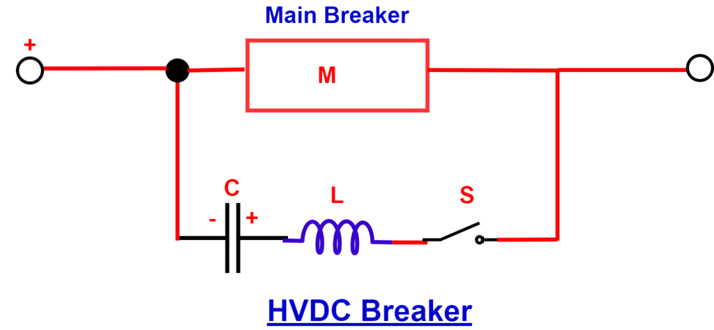
A capacitor C, which has already been charged, is connected with its polarities reversed, as shown in the figure. An inductor L and a switch S are connected in series with the capacitor C. This additional circuit is then connected in parallel with the main breaker M.

When everything is working normally, switch S is open, and the main breaker M is closed, allowing current to flow through. However, if there is a fault current or disruption, switch S will close and complete the LC circuit, causing the main breaker M to open.
During this period, the capacitor C begins to discharge, causing the current to flow in the opposite direction through the breaker M. This causes the arcing current to oscillate and eventually reach a zero point, resulting in artificial commutation or zero crossing. The LC circuit generates this artificial zero commutation, which allows the arc to extinguish at the zero current point. The excess energy is dissipated within the LC circuit.
This type of DC circuit breaker can function on a single power line and does not require a second line with an opposite polarity.
Method 2:
Here’s an explanation of another method for quenching arcs in HVDC circuit breakers that uses both lines of a DC transmission.
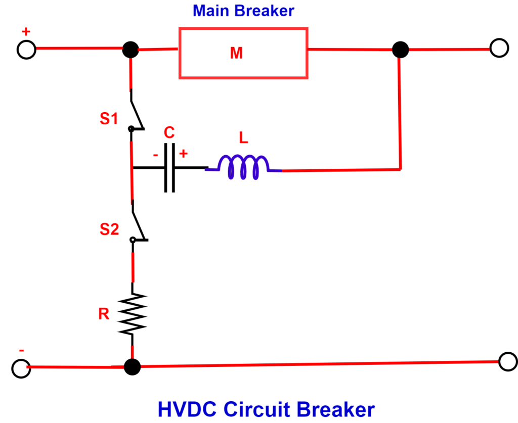
In this method, the main breaker M is connected to the live or hotline. An LC circuit is connected in parallel with the main breaker M using two switches, S1 and S2. The S2 switch connects the LC circuit to the ground through a high-resistance R.
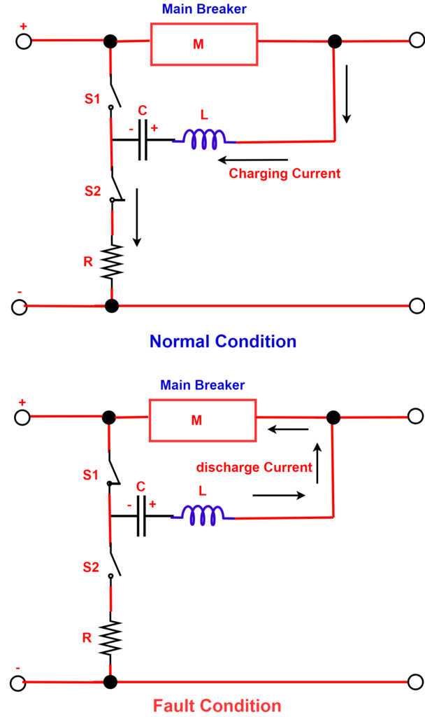
Under normal conditions, the main breaker M & the switch S2 is closed, while the S1 is open. The current flows through the main breaker M to the load & also through the switch S2 to charge the capacitor. The capacitor is charged through high resistance.
During an interruption or fault current, the switch S2 is opened, and the S1 is closed. The charged capacitor begins to discharge in the reverse direction through the main breaker M. The LC circuit starts to resonate and create an oscillating current, which pushes the current through the main breaker M to cross zero.
When the current in the circuit reaches zero, the main breaker’s contacts (M) separate, which causes the electrical arc to extinguish. Following the opening of M contacts, switch S2 is closed while S1 is opened. S2 allows any remaining energy to dissipate through a heavy resistance, R, which prevents the electrical arc from reoccurring.
Applications of HVDC Circuit Breaker
The applications of HVDC power go beyond power transmission and include technology. HVDC circuit breakers are necessary for some of these applications.
Photovoltaic Plants:
A photovoltaic plant is composed of multiple strings of photovoltaic panels that convert solar energy into DC electrical energy. These panels generate DC electrical energy when exposed to solar radiation. Photovoltaic plants are used to offer renewable energy to both small households and large industries. Multiple photovoltaic panels are combined to increase voltage and current ratings for powering large compounds.
The equipment required to handle high voltage, such as converters and batteries, can be very expensive. Thus, it must be protected from fault conditions. Multiple DC circuit breakers are used to isolate different parts of the system in case of faults or maintenance to avoid any damage or harm to individuals.
Electric Traction:
DC power has proven to be highly useful in the field of electric traction, primarily because of the speed-torque relation of DC motors. A wide range of vehicles, like electric trains, trams, and trolleybuses, use DC motors. One of the significant advantages of DC supply is that it uses a single conductor to supply current to the vehicle while the rail serves as the current return path. This approach also reduces the number of conductors required for such systems.
The DC power has found one of its best uses in the field of electric traction because of the speed-torque relation of the DC motor. The electric trains, trams & trolleybuses use DC motors. The advantage of DC supply is using a single conductor that supplies current to the vehicle while the rail is used as the current return path. Thus, it also reduces the number of conductors. Therefore, it is necessary to install proper protection systems to safeguard all equipment. As a result, multiple DC circuit breakers are employed to protect each system.
HVDC Power Transmission:
High-voltage direct Current (HVDC) is a technology that enables power transmission over very long distances. The conversion of DC to AC or vice versa requires specialized terminals that are quite expensive and must be protected at all costs. Fault currents can easily damage any equipment connected to the power transmission, so it’s crucial to take appropriate measures to prevent such incidents.
Therefore, HVDC circuit breakers are installed in transmission lines to protect against fault current and isolate the line for maintenance work.
MTDC Grid Systems:
MTDC is a complex HVDC transmission system used for power transmission, flexibility & control over multiple grids.
The MTDC, as its name suggests, connects multiple terminals, resulting in multiple circuit branches. In the event of a fault or scheduled maintenance in a particular branch, it needs to be de-energized using a circuit breaker. Therefore, separate HVDC circuit breakers are used for different branches.