Learn how earthing is done step-by-step, from site evaluation and electrode selection to testing and compliance. Ensure safety and system protection with proper earthing methods.
Have you ever felt a mild electric shock when touching an appliance while it’s running?
These minor shocks can sometimes indicate serious electrical issues and, in some cases, may lead to dangerous accidents. To prevent such hazards, proper earthing of electrical systems in buildings is essential.
Earthing is the process of safely discharging excess or leakage current into the ground. It provides a controlled path for fault current to flow, preventing electric shocks, equipment damage, and fires. Similarly, grounding helps stabilize the electrical system and manage load imbalances during overvoltage or fault conditions.
What is Earthing?
Earthing is defined as:
“The process in which the instantaneous discharge of electrical energy occurs by transferring charges directly to the earth using a low-resistance wire.”
A low-resistance path is crucial to allow fault current to flow safely into the earth, minimizing potential damage and ensuring user safety.
Electrical earthing refers to the process of connecting the non-current-carrying parts of electrical equipment or the system’s neutral point to the ground. This connection offers a low-resistance path for any leakage or fault current to safely dissipate into the earth.
Galvanized iron (GI) is widely used as the earthing conductor due to its durability and conductivity. By directing fault currents into the ground — which is at zero potential — electrical earthing safeguards both the equipment and the entire system from damage caused by short circuits or insulation failures.
How is Earthing Done?
Earthing is typically implemented by connecting electrical equipment to an earthing system or earth electrodes that are buried in the soil.

The setup usually includes an earthing mat or electrode made of conductive materials (such as copper or galvanized iron) with a flat iron riser, buried below ground level. This system is connected to all non-current-carrying metal parts of electrical installations to ensure any fault current is diverted safely into the ground.
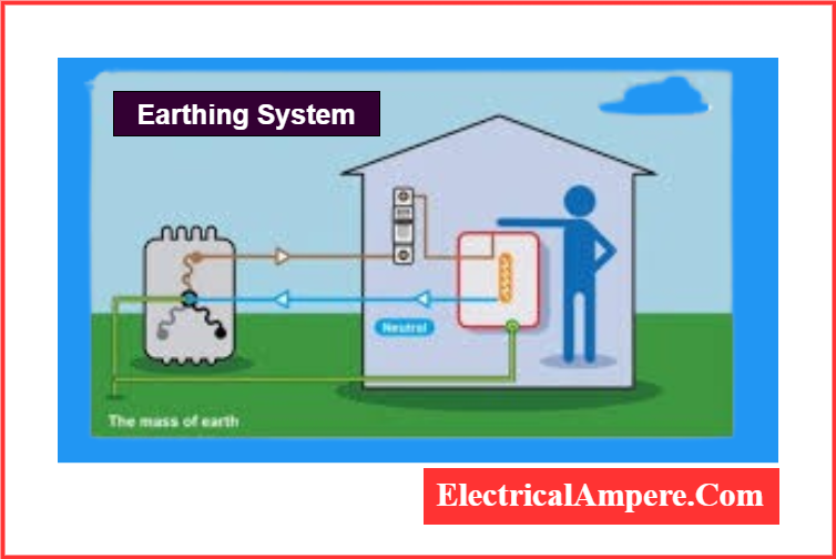
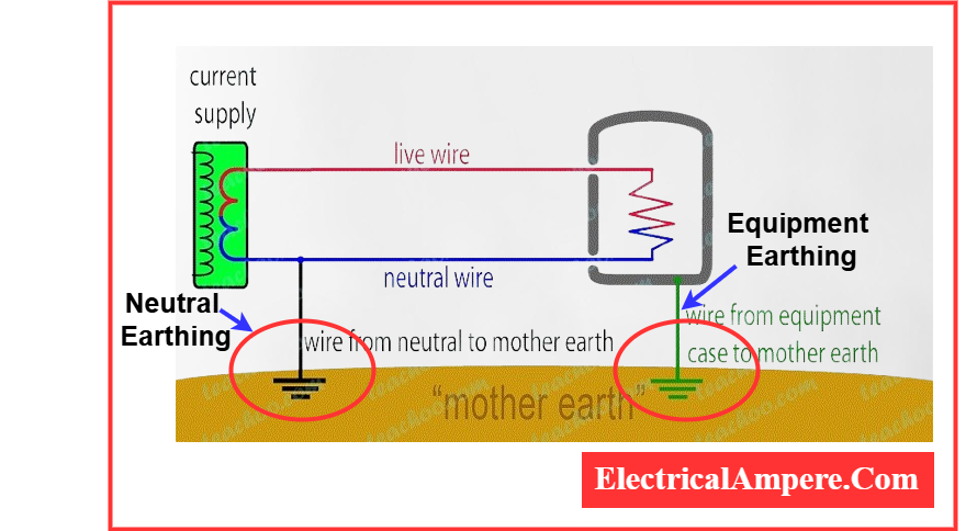
The illustration below demonstrates how an earthing system is integrated into a typical electrical setup.
When an overload current flows through electrical equipment or a fault occurs in the system, the fault current is safely diverted through the earthing system. The earth mat conductors help manage this by raising the ground potential in proportion to the product of the earth mat resistance and the fault current. This mechanism plays a crucial role in protecting equipment from damage caused by overloads or fault currents.
In residential wiring systems, three types of wires are typically present: live, neutral, and earth.
- The live and neutral wires carry current to and from the power station.
- The earth wire is connected to a metal plate or rod buried in the ground.
Electrical appliances such as refrigerators, irons, and televisions are connected to the earth wire during operation. This ensures that in the event of a surge or fault, the excess current is safely discharged into the earth, thereby protecting the user and the device.
In most homes, local earthing is provided near the main electrical meter to ensure proper grounding of the entire household electrical system.
Types of Earthing
There are three primary types of earthing systems commonly used in electrical installations:
1. Pipe Earthing
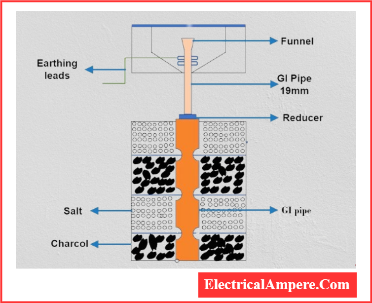
Pipe earthing is the most widely adopted and cost-effective method. It involves inserting a galvanized steel pipe (typically 38 mm in diameter and about 2 meters in length) vertically into the ground. This pipe acts as the earth electrode, effectively dissipating fault currents into the soil. Due to its simplicity and efficiency, this method is extensively used in residential and commercial installations.
2. Plate Earthing
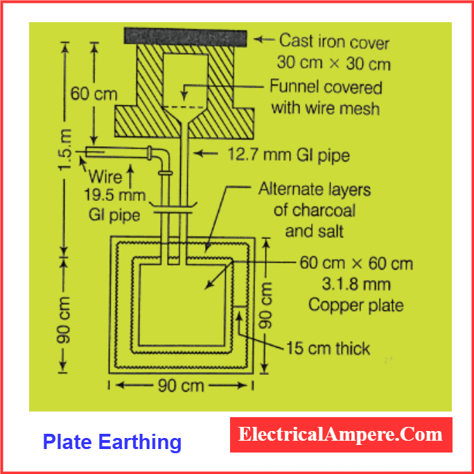
In plate earthing, a copper or galvanized iron (G.I.) plate is buried vertically at a depth of at least 3 meters below ground level. The plate is surrounded by alternate layers of charcoal (coke) and salt, which help retain soil moisture and improve conductivity. This type of earthing is commonly used where soil conductivity is relatively low.
3. Strip or Wire Earthing
This method is mainly used for high-voltage transmission and distribution systems. It involves laying strip electrodes (minimum cross-section of 25 mm × 1.6 mm for copper or 25 mm × 4 mm for G.I. or steel) horizontally in trenches at a depth of at least 0.5 meters. Strip earthing provides a low-resistance path for fault currents over long distances.
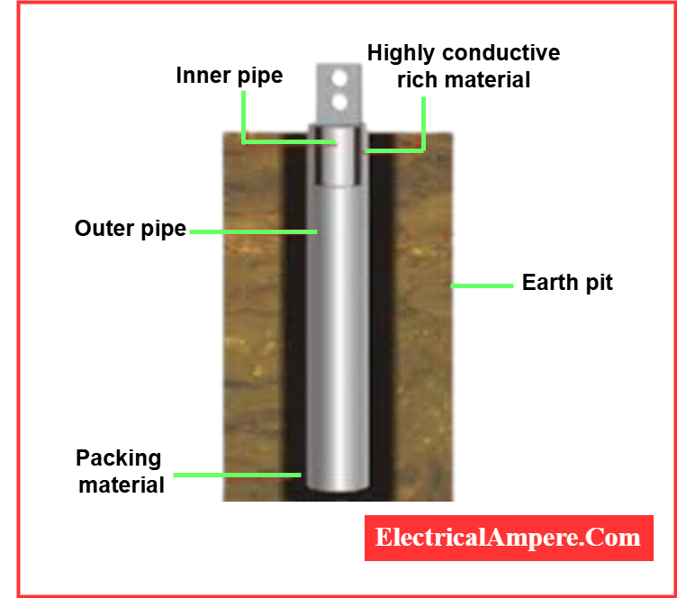
4) Rod Earthing

Rod earthing involves driving a galvanized steel pipe or copper rod vertically into the ground, either manually or with the help of a hammer, to achieve the required earth resistance. The deeper the electrode is inserted, the lower the resistance to earth.
This method effectively channels fault current safely into the ground by embedding the rod to a sufficient depth, ensuring solid contact with the surrounding soil.
Rod earthing is cost-effective and particularly suitable for areas with sandy or loose soil. However, in regions with highly resistive soil, its performance is generally inferior to that of plate earthing or other advanced earthing techniques.
Types of Electrical Earthing Based on Function
There are two primary components of electrical equipment that do not conduct current: These components, though non-conductive, do not impact the functionality of the electrical equipment or its frame.
Based on the earthing of these two non-current-carrying components, two distinct types of earthing are:
1) Neutral Earthing
Neutral earthing involves connecting the system’s neutral point directly to the earth using a GI wire.
This form of earthing is also referred to as system earthing and is commonly used in systems with star winding configurations. Electrical equipment such as generators, transformers, and motors often come with neutral earthing integrated into their design.
2) Equipment Earthing
Equipment earthing focuses on grounding the metallic frame and other non-current-carrying parts of electrical equipment. These parts are connected to the earth through a conducting wire.
In the event of a malfunction, this earthing method allows the fault current to safely flow to the ground, thereby protecting the system from potential damage.
Additional Notes:
- Earthing is an essential safety measure to prevent electric shock.
- Electrical wiring in homes typically consists of three wires: live, neutral, and earth.
- Earth mat conductors help maintain a consistent voltage value.
- Earthing strips are particularly useful in transmission systems.
- Earthing protects us by acting as a direct path for fault currents to flow safely to the ground.
Earthing System Components
The effectiveness of an earthing system depends heavily on the resistivity of the soil. Various materials and components are used to ensure optimal conductivity and safety. The key components of an earthing system include:
1) Earth Electrodes
To minimize earth resistance, a ring or mesh of bare, buried horizontal conductors is typically used. These horizontal conductors are often supplemented with vertical electrodes driven into the ground. The combination enhances the surface contact area and provides a more reliable path for fault current dissipation.
2) Earth Pits
Earth pits serve as inspection and testing access points for the earthing system. They are generally installed outside buildings or installations. At the base of the earth pit, an accessible device is installed to disconnect earth conductors when required for maintenance or testing. These pits are clearly marked with an earth symbol or sign to indicate their purpose.
3) Permanent and Mechanical Earth Bonds
Reliable and durable electrical connections are vital in any earthing system. To ensure long-lasting performance:
- Aluminothermic welding is recommended. This welding method relies on a chemical reaction that creates a molecular bond between metallic conductors, offering superior mechanical strength, electrical conductivity, and corrosion resistance compared to traditional mechanical connections.
- The use of tablet-form welding material and remote electronic initiator kits improves the efficiency, safety, and cost-effectiveness of installation.
4) Conductivity Enhancers (or Boosters)
In areas where soil resistivity is high, achieving a low earth resistance value can be challenging, even with multiple electrodes. In such cases, conductivity enhancers are used. These materials:
- Retain soil moisture.
- Provide long-term ion exchange.
- Lower the resistance of the soil significantly.
- Are corrosion-free and durable.
Conductivity boosters are particularly valuable in rocky, sandy, or dry soil conditions.
Earthing Procedure
Step-by-Step Guide for Earthing System Installation
Implementing an effective earthing system is crucial for ensuring safety and system stability. Below is a structured procedure for proper earthing installation:
Step 1: Site Evaluation and Preparation
- Identify the ideal location for the earthing system based on soil resistivity, moisture content, and proximity to the electrical infrastructure.
- Clear the site of any debris, rocks, or obstructions to facilitate smooth installation.
Step 2: Selection of Earthing Electrodes
- Choose the appropriate type of earthing electrodes (e.g., pipes, rods, or plates) based on:
- Soil characteristics
- Available installation space
- Desired resistance level
- Determine the number and dimensions of electrodes required to meet the targeted earth resistance value.
Step 3: Installation of Electrodes
- Dig a trench or pit of sufficient depth and diameter according to the selected electrode type.
- Install the electrodes vertically or horizontally, ensuring firm contact with the soil to enhance conductivity.
- Use copper wires or strips to interconnect electrodes, ensuring all connections are secure and corrosion-resistant.
Step 4: Jointing and Bonding
- Use exothermic welding (aluminothermic) or compression connectors to join electrodes and conductors for durable, low-resistance bonding.
- Connect the earthing system to the electrical installation using low-resistance connections to facilitate effective current flow.
Step 5: Testing and Verification
- Perform earth resistance tests using a digital earth resistance tester to confirm the system meets required values.
- Conduct a continuity test to verify the integrity of all connections and ensure a continuous path for fault current.
Step 6: Documentation and Maintenance
- Record all installation steps, including layout diagrams, resistance values, and test reports.
- Schedule periodic inspections to check for corrosion, loosening, or damage. Perform maintenance to retain system reliability.
Step 7: Certification and Compliance
Obtain certification or approvals from regulatory authorities or third-party auditors if required.
Ensure the installed earthing system adheres to relevant IEC, IS, or local standards and safety regulations.
What are the 5 IEC Types of Earthing Systems?
According to IEC 60364, all electrical power distribution systems are categorized into one of the following five earthing types:
- TN-S System
- TN-C-S System
- TN-C System
- TT System
- IT System
These classifications are also defined under BS 7671 (IET Wiring Regulations) and are essential for understanding how the earth and neutral are managed within an electrical installation.
Meaning of Abbreviations:
- T = Terre (French for Earth) – Connection to the earth.
- N = Neutral – The return path in the electrical system.
- S = Separate – Neutral and protective earth conductors are separated.
- C = Combined – Neutral and protective earth conductors are combined.
- I = Isolated – The system is isolated from earth or connected through a high impedance.
1. TN-S (Terre-Neutral Separate) System
- The neutral (N) and protective earth (PE) conductors are separate throughout the system.
- Earth connection is provided at the source.
- Common in residential and commercial installations for its safety and noise reduction.
2. TN-C-S (Terre-Neutral Combined-Separate) System
- The neutral and earth conductors are combined in part of the system and then separated closer to the consumer premises.
- Also known as Protective Multiple Earthing (PME).
- Widely used in utility networks.
3. TN-C (Terre-Neutral Combined) System
- The neutral (N) and protective earth (PE) are combined throughout the entire system (called PEN conductor).
- Less safe due to lack of dedicated earth conductor.
- Mostly restricted to certain industrial or temporary setups.
4. TT (Terre-Terre) System
- The power source has its own earth connection, and the consumer provides a separate local earth electrode.
- No connection between source and consumer earth.
- Suitable where the utility cannot provide a reliable earth.
5. IT (Isolated Terre) System
- The power system is either isolated from earth or connected through a high impedance.
- No direct connection between the system and earth.
- Mostly used in critical systems like hospitals, mines, or industrial automation, where continuity is more important than fault interruption.
Summary Table:
| System | Earth at Source | Earth at Load | Neutral & Earth | Application |
|---|---|---|---|---|
| TN-S | Yes | Shared | Separate | Residential, Commercial |
| TN-C-S | Yes | Shared | Combined then Separate | Utilities, Mixed Systems |
| TN-C | Yes | Shared | Combined | Industrial, Temporary |
| TT | Yes | Separate | Separate | Rural, Isolated Areas |
| IT | No (or Impedance) | Local | Isolated | Critical/Medical Installations |
Advantages of Earthing
- Enhanced Safety: Earthing protects both users and equipment by offering a safe path for fault currents to dissipate, thereby minimizing the risk of electric shocks.
- Neutral Reference: Since the earth’s potential is considered zero, it acts as a neutral reference point, ensuring stability in electrical systems.
- Device Protection: Proper earthing prevents damage to electrical appliances during voltage surges or overloads, enhancing their lifespan.
- Fire Prevention: Leakage currents can cause sparking, which may lead to electrical fires. A well-designed earthing system helps prevent such hazards.
- Unrestricted Use of Metal: Metals used in installations don’t need to be perfectly non-conductive because proper earthing ensures that any stray current is safely grounded.
Note: While the terms earthing and grounding are often used interchangeably, there are subtle differences based on regional usage and application.
Disadvantages of Earthing
While earthing is a fundamental safety mechanism in electrical systems, it does come with certain limitations:
1. High Installation and Maintenance Costs
The initial setup of a proper earthing system—especially in industrial or high-voltage installations—can be expensive. This includes the cost of quality electrodes, conductors, trenching, and periodic maintenance.
2. Safety Hazards During Installation
If not done correctly, the earthing installation process can pose safety risks to workers. Improper handling, inadequate personal protective equipment (PPE), or inaccurate soil resistivity assessments can lead to accidents.
3. Space Requirements
Some earthing methods like strip or plate earthing require significant land area and depth, which may not always be feasible in urban or space-constrained environments.
4. Performance Depends on Soil Conditions
The efficiency of earthing is heavily influenced by soil resistivity, moisture content, and temperature. In areas with dry or rocky soil, achieving low resistance values may require advanced and expensive enhancements.
Applications of Earthing
Earthing systems play a vital role across a wide range of applications, from domestic households to large-scale power networks:
1. Residential Installations
Earthing is crucial in homes to protect against electric shocks and equipment damage. Appliances such as refrigerators, TVs, and washing machines are earthed to safely discharge any leakage current.
2. Voltage Stabilization in Low Voltage Systems
Fluctuations in voltage are common in residential areas. Proper earthing helps stabilize the voltage level by providing a zero-potential reference, thereby reducing the impact of voltage surges on household devices.
3. High Voltage Systems (>1kV)
In high voltage applications, earthing focuses less on personal safety and more on:
- Ensuring system reliability
- Maintaining equipment integrity
- Managing fault conditions
The line-to-ground (L-G) fault is the most common fault type in HV systems. During such faults, earthing offers a path for the fault current to flow into the ground, allowing protective devices to isolate the faulted section efficiently.
Frequently Asked Questions (FAQ) on Earthing
1). What are the 4 Types of Earthing?
The commonly used types of earthing systems include:
- Plate Earthing – Involves burying a copper or GI plate in the ground surrounded by salt and charcoal.
- Pipe Earthing – Utilizes a galvanized iron pipe placed vertically into the ground; it is one of the most effective and economical methods.
- Rod Earthing – Uses copper or GI rods driven into the soil to disperse fault current.
- Strip Earthing – Involves the use of metal strips or wires laid in trenches, often used in high-voltage and transmission systems.
2). What is the Principle of Electrical Earthing?
The basic principle of electrical earthing is to provide a safe path for fault current to flow directly into the ground. By connecting non-current-carrying metallic parts to the earth, it ensures that dangerous voltages do not pose a risk to humans or equipment, thereby enhancing safety, reliability, and protection in electrical systems.
3). What are the Three Main Reasons for Earthing?
The primary reasons for implementing an earthing system are:
- Protection of people from electric shocks by ensuring fault current flows into the ground.
- Safe discharge of excessive current during electrical faults or lightning strikes.
- Protection of electrical equipment and buildings from potential damage, fires, or structural collapse due to voltage surges.
4). What is the Method of Electrical Earthing?
There are several methods for earthing based on the site and application:
- Pipe Earthing (most widely used)
- Plate Earthing
- Rod Earthing
- Strip or Wire Earthing
- Water Main Earthing (less common today)
The selection depends on factors like soil resistivity, installation type, and current-carrying requirements.
5). Why is Salt Used in Earthing?
Salt is mixed with charcoal and soil in earthing pits to enhance the conductivity of the surrounding soil. Salt attracts moisture and helps maintain low resistance around the electrode, ensuring efficient fault current dissipation into the ground—even in dry or rocky areas.
Read Next: