Explore the complete guide on DC series motor covering its working principle, construction, detailed diagrams, speed control methods, and common applications. Learn why the DC series motor is ideal for high-torque, heavy-load industrial and vehicle uses.
A DC series motor—often referred to as a series wound DC motor—is a popular type of direct current motor where the field winding is connected in series with the armature winding. Its unique structure makes it ideal for applications requiring high starting torque.
Introduction to DC Series Motor
A DC series motor is a type of self-excited motor in which the field winding is connected in series with the armature winding. This configuration ensures that the same current flows through both, producing a magnetic field directly proportional to the armature current. The motor is mainly made up of two key components—the stator and the rotor—which interact both electrically and magnetically. This design gives the series wound motor its signature feature: exceptionally high starting torque, ideal for heavy-load applications.
Series Wound DC Motor Definition:
A DC motor in which the field winding is connected in series with the armature winding, providing high starting torque and variable speed.
Construction of Series DC Motor
The components of a series wound DC motor are mainly divided into three parts:
- Stator
- Armature
- Brushes
Stator
The stator is the stationary part of the DC series motor. It provides the magnetic field needed for motor operation. It consists of two main components:
- Yoke(Frame)
- Field Windings
Yoke (Frame)
The yoke serves two primary functions:
- Structural Frame: It acts as the outer shell of the motor, providing mechanical support to the field poles and maintaining the motor’s overall rigidity and alignment.
- Magnetic Path: It forms a low-reluctance magnetic return path for the flux generated by the field windings, ensuring efficient magnetic circuit operation.
Unlike some motors that use a solid cast iron frame, series wound DC motors often have their yoke made from laminated rolled steel sheets. This laminated construction reduces eddy currents—unwanted parasitic currents induced by changing magnetic fields—that cause heat loss and reduce efficiency. By minimizing eddy currents, the laminated yoke helps improve the motor’s performance and longevity.
Field Windings
The field winding is generates the magnetic field in a DC series motor. Typically, these windings are made from thick, round copper wires with a high current-carrying capacity. However, for high-performance DC series motors, alternative wire shapes like rectangular or square copper conductors are sometimes used. These shapes improve packing density within the limited space available for the windings, allowing more turns and creating a stronger magnetic field. This enhances the motor’s efficiency and torque performance.
Armature
The armature is the rotating part of the DC series motor and plays a crucial role in energy conversion. It consists of:
- Core
- Armature Windings
- Commutator
- Shaft
Core
The armature core in a DC series motor is a key rotating component that holds the armature windings and enables torque production. Like the stator frame, it is built from laminated steel sheets to minimize eddy current losses. These laminations help improve efficiency by reducing heat buildup.
In high-torque series wound DC motors, the core design may include slotted and skewed slots. Skewing the slots slightly off the axis helps reduce cogging torque, which is the jerky motion caused by uneven magnetic interaction. This results in smoother motor rotation and better performance.
Armature Windings
The armature winding is the active conductor in the DC series motor that plays a central role in torque generation. Typically made from insulated copper wire, it is placed in slots on the armature core. For standard applications, round copper wire is used, while rectangular or square conductors are preferred in high-power motors to improve packing density and magnetic efficiency.
Depending on motor design, lap or wave winding patterns may be employed. These configurations affect the number of poles formed, the back EMF, and the overall motor performance.
Commutator
The commutator in a DC series motor is the rotary switch that directs current through the armature windings, ensuring the torque remains unidirectional. It comprises multiple copper segments mounted on the motor shaft and insulated from one another. It maintains continuous electrical contact by allowing carbon brushes to slide over its segmented surface, enabling the current to switch direction and keep the motor spinning smoothly.
Traditionally, commutator segments were made from solid copper. Modern designs often enhance this by silver-brazing the contact surfaces where brushes meet the copper. This silver layer offers superior wear resistance and corrosion protection, reducing sparking and extending the commutator’s service life. By precisely reversing current every half revolution, the commutator enables smooth conversion of DC power into mechanical rotation.
Shaft
The shaft is a central mechanical part of the DC series motor, responsible for transferring rotational motion to the external load. The armature is mounted on the shaft, and the shaft’s ends are supported by two bearings—one at each side—for smooth and stable rotation. On the drive end, a coupling is mounted to connect the motor to mechanical loads such as gears, pulleys, or wheels. The shaft is typically made of high-strength steel to handle mechanical stress and ensure long-term durability.
Brushes
Brushes in a DC series motor are sliding electrical contacts that transfer current to the commutator. They are typically made from carbon or graphite because of their good conductivity and self-lubricating properties. For higher performance or critical environments, brushes made from a combination of copper and graphite, known as metal graphite brushes, are used. These brushes offer improved current carrying capacity and reduce sparking compared to pure carbon brushes.
The brushes press firmly against the commutator segments, allowing smooth current flow into the armature windings as the motor rotates. Since the brushes carry the same current flowing through both the field and armature windings in a series motor, their quality and proper positioning are vital for efficient operation and long motor life.
DC Series Motor Diagram
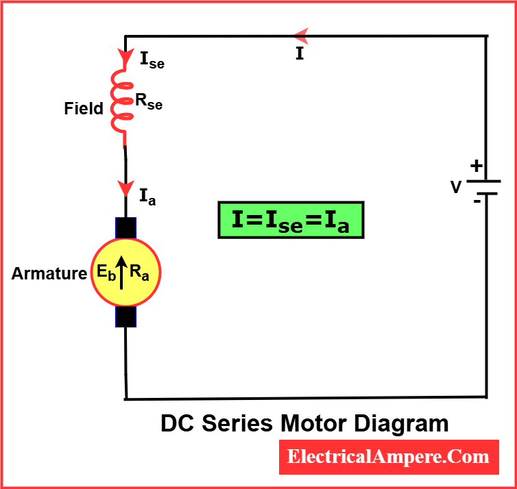
In a DC series motor connection, the field and armature are directly connected in one loop. This means that the same current flows through both the field winding and the armature winding. The diagram of a DC series motor typically shows the armature winding and the series field winding connected in series with the DC power supply. Because the field winding is in series with the armature, the magnetic field strength varies directly with the armature current, which significantly influences the motor’s speed and torque characteristics.
DC Series Motor Working Principle
The working principle of a DC series motor is based on Faraday’s Law of electromagnetic induction and the Lorentz force. When a voltage is applied, current flows through the series-connected field and armature windings, producing a strong magnetic field.
Whenever a current-carrying conductor (the armature coils) is placed in this magnetic field, it experiences a force called the Lorentz force. This force causes the armature—the rotating part of the motor made of wire coils—to turn. The magnetic field created by the armature interacts with the magnetic field from the field windings (electromagnets), generating torque.
This torque makes the motor shaft rotate, delivering mechanical power to drive loads like pumps, fans, or other machinery. Due to the series connection, the motor produces high starting torque, making it ideal for applications requiring strong initial force.
DC Series Motor Equations
To understand the equations of a DC series motor, let’s first look at a diagram of the motor.

Voltage Equation
The voltage equation for a series wound DC motor is similar to that of other DC motors and is given by:

Where:
- V = Applied voltage
- Eb = Back EMF (Electromotive Force)
- Iₐ = Armature current
- Ra = Armature resistance
- Rse = series field winding resistance
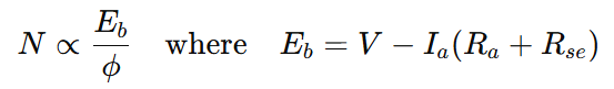
Speed Equation
The speed N of a DC series motor is inversely proportional to the magnetic flux ϕ and directly proportional to the back EMF Eb. The speed equation of the motor is,

Where:
- N: Speed of the motor
- K: Constant
- Eb: Back EMF
- V: Supply voltage
- Ia: Armature current
- Ra: Armature resistance
- Rse: Series field resistance
- ϕ: Magnetic flux per pole
Torque Equation
The torque equation of a DC series motor is based on the fact that the torque T is directly proportional to the product of the flux ϕ and the armature current Ia. In a series motor, both the field flux and armature current are in series, so:

This means that torque increases rapidly with armature current, giving DC series motors high starting torque.
Torque-Speed Relation of a DC Series Motor
In a series wound DC motor, torque is directly related to the armature current. As the armature current increases, the magnetic field generated by the field winding becomes stronger. This stronger magnetic field interacts more powerfully with the current flowing through the armature conductors, producing a greater force and, therefore, higher torque.
Because of this characteristic, series wound DC motors provide very high starting torque, making them ideal for applications requiring a strong initial push, such as heavy industrial machinery like cranes or large metal processing equipment. However, these motors are typically operated only for short durations, mainly during startup.
Understanding the relationship between speed and torque in a series wound DC motor is crucial for choosing the right motor for your application, ensuring efficient and effective performance.
Characteristics of DC Series Motor
In a DC series motor, the field winding is connected in series with the armature, so it carries the full armature current. When the load on the motor shaft increases, the armature current rises accordingly. As a result, the magnetic flux in the motor also increases with the armature current, and it decreases when the armature current reduces.
Torque and Armature Current Characteristics
In a DC series motor, the armature torque τa is proportional to the product of flux ϕ and armature current Ia:

Up to magnetic saturation, the flux ϕ is proportional to the armature current Ia:

So, the torque becomes proportional to the square of the armature current:


This means the torque versus armature current curve up to magnetic saturation is a parabola (represented by part OA of the curve).
After magnetic saturation, the flux ϕ becomes constant, so the torque is directly proportional to the armature current:

Thus, the torque versus armature current curve beyond magnetic saturation is a straight line (part AB of the curve).
From this torque-current relationship, it is clear that the starting torque of a DC series motor is very high, making it ideal for applications that require strong initial torque.
Speed and Armature Current Characteristics
The speed N of a DC series motor is given by:
As the armature current Ia increases, the back EMF Eb decreases due to the voltage drop across the armature and series field resistances. At the same time, the flux ϕ increases because the field winding carries the full armature current.
Under normal operating conditions, the resistance drop Ia(Ra+Rse)is very small and can often be neglected. Thus, up to magnetic saturation, speed is inversely proportional to the flux, and since flux ϕ is proportional to armature current Ia:

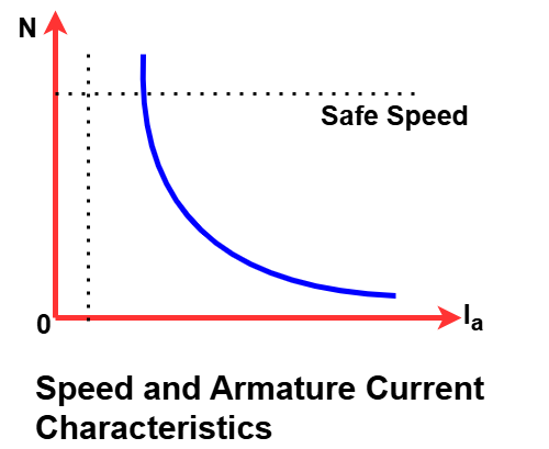
Therefore, the speed versus armature current curve up to magnetic saturation is a hyperbola. After magnetic saturation, the flux becomes constant, and the speed tends to stabilize accordingly.
Speed and Torque Characteristics
The speed-torque characteristics of a DC series motor can be derived by combining its speed–armature current and torque–armature current relationships.
For a specific armature current Ia, determine the corresponding torque τa from the torque–armature current curve and the speed N from the speed–armature current curve. This gives a point (τ,N) on the speed-torque curve. Repeat this for various values of armature current to obtain multiple points like (τ1,N1),(τ2,N2), etc.
Plotting these points creates the speed-torque characteristic curve of the DC series motor.

From this curve, it is evident that the DC series motor produces high torque at low speeds and low torque at high speeds. This makes it ideal for applications requiring high starting torque.
Speed Regulation of DC Series Motor
Speed regulation of a motor refers to the ability of a motor to maintain a constant speed as the load varies. It is usually expressed as a percentage difference between no-load speed and full-load speed, relative to full-load speed. Lower values indicate better (tighter) regulation.
The DC series motor exhibits poor speed regulation, meaning its speed varies significantly with load changes—typically by 30% to 50% or more. This makes it unsuitable for applications requiring precise and stable speed control.
DC series motors have poor speed regulation because their speed decreases significantly as load increases. This happens because an increase in load causes higher armature current, higher armature current means higher field current which strengthens the magnetic field and reduces speed. Conversely, with little or no load, the current drops, weakening the field and causing the speed to rise dangerously high.
Practical Safety Notes:
- Never run the motor without a load: Because the motor speed can increase dangerously when unloaded, this can cause mechanical damage or pose safety risks due to excessive RPMs.
- Use appropriate load monitoring: Always ensure the motor operates under a sufficient load to prevent runaway speeds.
- Implement protective devices: Use speed limiters, overload relays, or safety cutoffs to avoid accidents caused by sudden speed surges.
- Regular inspection of brushes and commutator: Poor speed regulation combined with brush sparking can create fire hazards, especially in explosive atmospheres.
For a detailed explanation and examples, read our complete guide on speed regulation of DC motor
Speed Control of DC Series Motor
Speed control in DC series motors is vital for applications requiring flexibility in performance. The speed of the motor depends primarily on two factors: the flux (ϕ) produced by the field winding and the back EMF (Eb) developed in the armature. Controlling either of these parameters allows speed control. There are three ways of speed control of DC series motor.
- Field Control Method( Flux Control)
- Armature Resistance Control Metod
- Voltage Control method
Field Control Method (Flux Control)
Field Resistance Control (Flux Control) adjusts motor speed by inserting a variable resistor in series with the field winding, reducing flux and increasing speed, though inefficiently. The following methods of field resistance control are used:
Field Diverter Control
- A variable resistor is connected in parallel with the series field winding.
- Diverts a portion of the armature current, weakening the magnetic field.
- As flux decreases, speed increases.
- Used in traction systems for controlled acceleration.
Armature Diverter
- A variable resistor is connected in parallel with the armature circuit.
- Part of the total current is diverted through the diverter resistor.
- Reduces armature current without affecting the field current.
- Leads to decreased torque and speed under load conditions.
- Helps achieve smoother control in braking or load-reduction operations.
- Commonly used in traction motors and industrial machines requiring variable torque.
Tapped Field Control Method
- The field winding is provided with taps at various points along its length.
- A switch or tap changer selects different numbers of turns in the field winding.
- Varying the number of active field turns alters the field strength (flux).
- As the number of turns decreases, the magnetic field weakens, and motor speed increases.
- Allows discrete speed steps rather than smooth variation.
- Commonly used in applications like electric trains and cranes where step-wise speed control is acceptable.
Armature Resistance Control Method
- A resistor is connected in series with the armature circuit.
- Reduces voltage across the armature, reduce back EMF, decreasing speed.
- Simple but inefficient due to power loss in the resistor.
- Suitable for limited-duty or temporary operations.
Armature Voltage Control Method
- Speed is directly proportional to the armature voltage (for a given flux).
- By adjusting the voltage applied to the armature, motor speed can be precisely controlled.
- This method provides high efficiency and better performance under load.
- A modern method using thyristors (SCRs) or chopper circuits to control the DC voltage applied to the motor.
- Provides smooth and efficient control of motor speed over a wide range.
- Allows for high-speed, low-speed, and even regenerative braking features.
- Common in industrial applications like electric traction and automation.
While traditional methods like field and resistance control are simple, they suffer from poor efficiency. Advanced methods like armature voltage control using thyristor drives offer better precision, energy efficiency, and are widely used in modern DC motor control systems.
Learn more in our detailed guide on speed control of DC series motor
Advantages of DC Series Motor
- High Starting Torque
The DC series motor provides a very high starting torque, which makes it ideal for applications requiring strong initial force, such as cranes, hoist and and electric traction. - Simple Speed Control
The speed of a DC series motor varies widely with load, which can be useful in applications where speed control is required without complex controllers. - Good Overload Capacity
It can handle occasional overloads without damage, making it reliable for heavy-duty applications. - Robust and Durable Construction
DC series motors are generally rugged and can operate in harsh environments. - Cost-Effective for High Torque Applications
Due to its simple design and high torque output, it is economical for certain industrial uses.
Disadvantages of DC Series Motor
- Poor Speed Regulation
Speed regulation is typically poor, often varying by 30% to 50% or more due to rising current and flux. This means the motor speed changes significantly with load, making it unsuitable for applications requiring precise speed control. - Not Safe to Run Without Load
Running the motor without load can cause dangerously high speeds, risking motor damage. - High Current Draw
The series connection can cause high armature currents, which may strain the power supply and require larger conductors. - Less Efficient
These motors may not be the most energy-efficient compared to other motor types. - Sparking Issues
Brushes can generate sparks when contacting the commutator, posing safety hazards in flammable or explosive environments. - More Frequent Maintenance
The brushes and commutator require regular maintenance due to wear, increasing upkeep efforts.
Application of DC Series Motor
The DC series motor is widely used in applications requiring high starting torque and where the load varies significantly during operation. Due to its characteristics—high torque at low speeds and speed variation with load—it is especially suited for devices that need strong torque to start but may operate at varying speeds.
Here are some common and practical uses:
- Traction Systems (Electric Traction Motors)
- DC series motors are commonly used in electric trains, trams, and trolleybuses.
- They provide the high starting torque required to accelerate heavy vehicles from rest.
- Their ability to handle large load changes makes them ideal for vehicles that frequently stop and start.
- Cranes and Hoists
- Cranes, hoists, and elevators require high torque to lift heavy loads.
- The DC series motor’s high starting torque ensures smooth lifting without stalling, and its speed changes with the load, allowing for safe and controlled operation.
- Electric Vehicles
- Early electric cars and forklifts have used DC series motors for propulsion.
- Their simple control and powerful torque at low speeds help in maneuvering and acceleration.
- Industrial Machines with Heavy Load Starts
- Machines such as metal cutting machines, printing presses, and conveyors utilize DC series motors to start under heavy loads.
- The motor adapts well to varying load conditions, making it reliable for such applications.
- Pumps and Blowers
- Certain types of pumps, fans, and blowers require variable speed control and torque.
- DC series motors are suitable when speed control is essential but the load may vary during operation.
- Electric Traction for Mining Equipment
- Mining equipment like underground loaders and dumpers also benefit from DC series motors.
- Their ability to generate high torque at startup is useful in tough terrains and heavy material handling.
Conclusion
The DC series motor remains a cornerstone of industrial and mechanical applications. Its ability to deliver high torque at startup makes it invaluable for machines like cranes, electric locomotives, and hoists. While it suffers from poor speed regulation and requires careful handling under no-load conditions, its performance under load is unmatched.
Understanding its construction, working principle, and series DC motor characteristics can help engineers choose the right motor for the right application.
Related Articles: