A DC generator is an electrical device designed to generate electricity by converting mechanical energy into electrical energy. Common sources of mechanical energy include:
- Hand cranks
- Internal combustion engines
- Water turbines
- Gas and steam turbines
- Wind turbines
DC generators play a crucial role in powering electrical networks. Interestingly, an electric motor operates as the reverse of a generator, converting electrical energy into mechanical energy. Since motors and generators share many similarities, understanding one helps in comprehending the other.
This article provides a brief overview of DC generators and their working principles.
What is a Generator?
A generator is a device that converts mechanical energy into electrical energy. The generated electricity is then transmitted and distributed through power lines for residential and commercial use.
Generators are broadly classified into two types:
- AC Generator (Alternating Current Generator) – Converts mechanical energy into alternating current (AC) electricity.
- DC Generator (Direct Current Generator) – Converts mechanical energy into direct current (DC) electricity.
Both types of generators play a vital role in power generation, catering to different applications based on their output characteristics.
What is a DC Generator?
A DC generator, or direct current generator, is an electrical device designed to convert mechanical energy into direct current (DC) electricity.
This energy conversion process is based on the principle of electromagnetically induced electromotive force (EMF). According to Faraday’s Law of Electromagnetic Induction, when a conductor moves through a magnetic field, it cuts the magnetic flux, inducing an electromotive force.
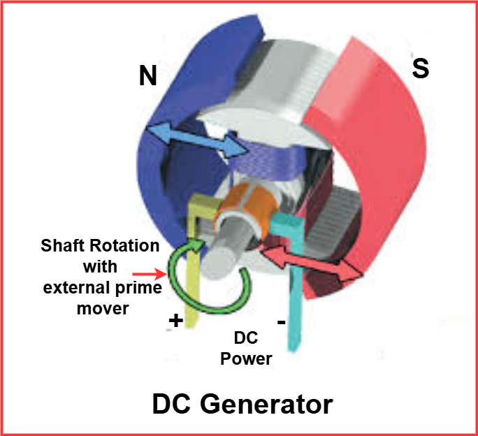
If the conductor circuit remains closed, this induced EMF drives a current, enabling the generation of usable DC electricity.
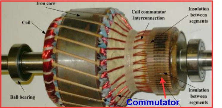
Construction of a DC Generator
A DC generator can also function as a DC motor without any design modifications. Due to this interchangeability, both devices are collectively referred to as DC machines.
Main Components of a DC Generator
A DC generator consists of several essential components, including:
- Yoke
- Poles
- Pole Shoes
- Field Winding
- Armature Core
- Armature Winding
- Commutator
- Brushes
Among these, the two most critical components of a DC generator are:
- Stator – The stationary part that houses the field windings and provides the necessary magnetic field.
- Rotor – The rotating part (armature) where the conversion of mechanical energy into electrical energy takes place.
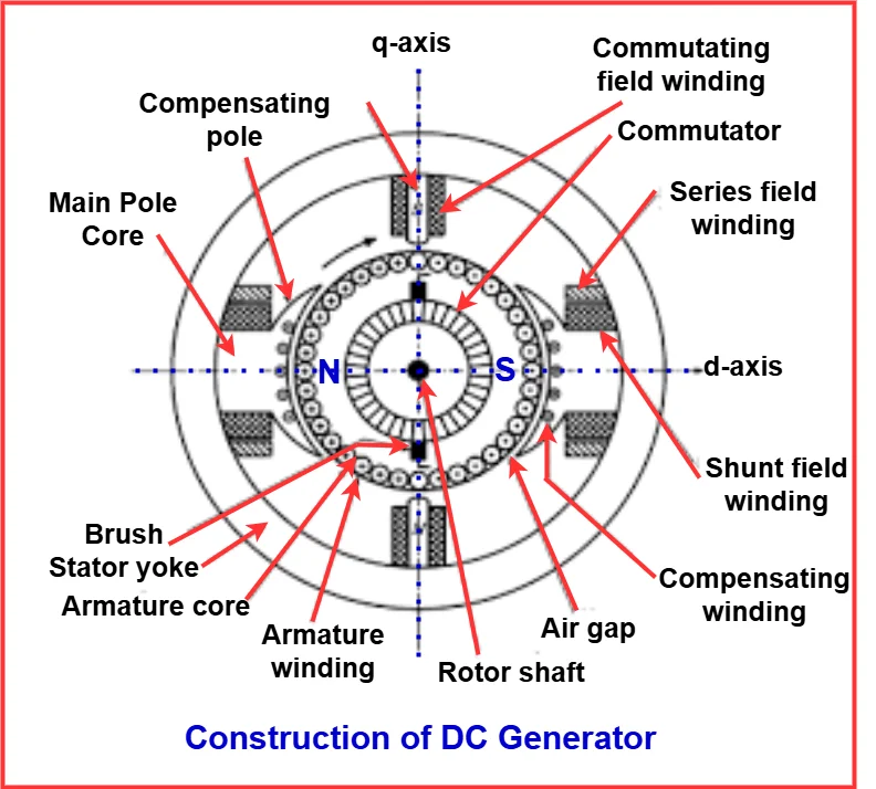
These components work together to ensure efficient energy conversion in a DC generator.
1. Stator
The stator is a crucial part of the DC generator, responsible for generating the magnetic field in which the armature coils rotate. It contains permanent magnets or electromagnets with north and south poles facing each other, positioned around the rotor region.
2. Armature Core (Rotor)
The rotor, also known as the armature core, is the rotating part of the DC generator. It is made of laminated iron sheets stacked together to form a cylindrical core with slots. These laminations help reduce eddy current losses, improving efficiency.
3. Armature Windings
The armature windings are placed inside the slots of the armature core. These windings are interconnected in a series-parallel combination to enhance the total generated current.
4. Yoke
The yoke is the outer frame of the DC generator, made of cast iron or steel. It serves two primary purposes:
- Provides mechanical support to the machine.
- Acts as a magnetic path to carry the magnetic flux between poles.
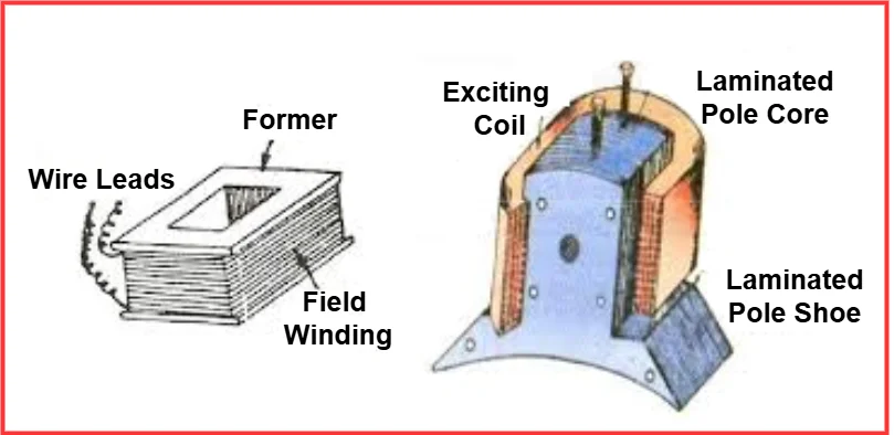
5. Poles
The poles are used to support and hold the field windings, which produce the magnetic field necessary for generating electricity. The field windings are wound around the poles and connected in series or parallel with the armature windings.
6. Pole Shoe
The pole shoe helps spread the magnetic flux evenly and provides mechanical support to prevent the field coils from shifting. Instead of screws, welding is often used to attach the pole shoes to the yoke.
7. Commutator
The commutator acts as a rectifier, converting the alternating current (AC) generated in the armature windings into direct current (DC) before it is supplied to the external circuit. It is made of copper segments, each insulated by mica sheets, and is mounted on the generator’s shaft.
8. Brushes
The brushes are made of carbon or graphite and are responsible for maintaining electrical contact between the commutator and the external circuit. They ensure smooth current transfer while minimizing wear and tear.
Each of these components plays a significant role in the efficient operation of a DC generator, ensuring reliable power generation.
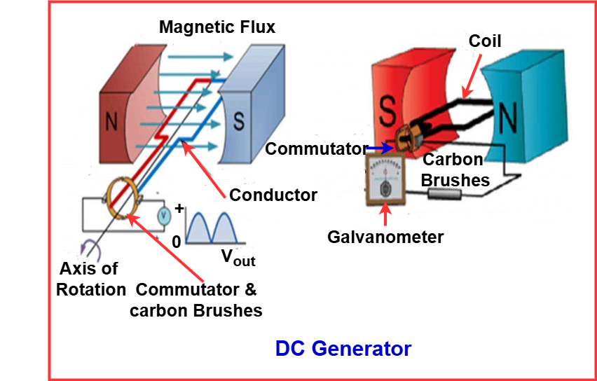
Commutator Function of a DC Generator
The commutator is an essential component of a DC generator, primarily responsible for converting alternating current (AC) into direct current (DC). It functions as a mechanical rectifier or a reversing switch, ensuring that the output current remains unidirectional.
The electromotive force (emf) induced in the generator’s armature windings is naturally alternating in nature. As the armature rotates, the direction of the current in the coil reverses when it crosses the magnetic neutral axis. However, the commutator reverses the connections of the coil at the precise moment the current would have changed direction. This switching action ensures that the current supplied to the external load remains DC rather than AC.
The commutator serves several key functions in a DC generator. Firstly, it enables the conversion of AC to DC, ensuring that the generator produces a steady direct current output. Secondly, it maintains unidirectional current flow by adjusting the coil connections, preventing current reversal in the external circuit.
Additionally, it facilitates smooth power transmission by ensuring a continuous and efficient transfer of electricity from the armature to the load. Lastly, working alongside carbon brushes, the commutator establishes a reliable electrical connection between the generator and the external circuit. Overall, the commutator plays a crucial role in ensuring the efficient and stable operation of a DC generator, making it suitable for various applications requiring a consistent DC power supply.
Working Principle of a DC Generator
A DC generator operates on the principle of Faraday’s Law of Electromagnetic Induction, which states that whenever a conductor is placed in a moving magnetic field, an electromotive force (emf) is induced in the conductor. If the circuit is closed, this emf causes a current to flow through the conductor.
According to Faraday’s Laws, an emf is induced in a conductor when it is either placed in a changing magnetic field or moved through a magnetic field. The magnitude of the induced emf can be calculated using the emf equation for a DC generator. If the conductor is connected to a closed circuit, the induced current will flow only within that circuit.
In a DC generator, the armature conductors rotate within the magnetic field created by the field coils. These field coils generate an electromagnetic field, and as the armature rotates, an electromagnetically induced emf is produced in the armature conductors. The direction of the induced current can be determined using Fleming’s Right-Hand Rule, which helps establish the relationship between the magnetic field, conductor motion, and induced current flow.
E.M.F. Equation of a DC Generator
The emf equation of a DC generator is derived from Faraday’s Laws of Electromagnetic Induction and is given by:
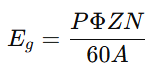
Where:
- Φ = Magnetic flux per pole (Weber)
- Z = Total number of armature conductors
- P = Number of poles in the generator
- A = Number of parallel paths in the armature
- N = Speed of the armature in revolutions per minute (r.p.m.)
- E = Induced electromotive force (emf) in any parallel path of the armature
- Eg = Generated emf in any one of the parallel paths
- N/60 = Number of turns per second
- dt = 60/N sec = Time for one turn
This equation helps in calculating the generated emf of a DC generator, which is crucial in determining the output voltage of the machine.
Efficiency of a DC Generator
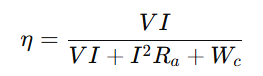
DC generators are highly reliable and efficient, with an efficiency range of approximately 85% to 95%. The efficiency of a DC generator is determined by comparing the output power to the input power while accounting for various losses.
The output power of a generator is given by:
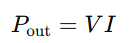
Where V is the voltage and I is the output current.
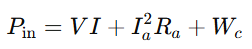
The input power includes the output power and internal losses, given by:
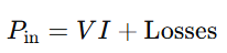
The losses in a DC generator consist of:
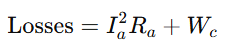
Where:
- Ia = Armature current
- Ra = Armature resistance
- Wc = Constant losses (such as core losses and mechanical losses)
Thus, the total input power becomes:
If the shunt field current is negligible, then Ia ≈ I, leading to the efficiency formula:
Rewriting,
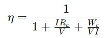
For maximum efficiency, the condition is derived by differentiating the loss term:
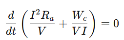
This results in:
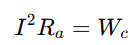
Thus, efficiency is at its maximum when the variable losses (I²Rₐ) are equal to the constant losses (Wₐ).
The load current at which the generator operates at maximum efficiency is given by:
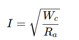
This equation helps determine the optimal operating conditions for a DC generator to ensure it functions at peak efficiency.
DC Generator Losses
In any electrical machine, a portion of the input energy is lost and cannot be fully converted into useful output power. Similarly, a DC generator experiences various energy losses, which can be categorized into different types.
1) Copper Loss
Copper loss occurs due to the resistance in the windings and is responsible for 20-30% of full-load losses. It includes:
- Armature copper loss: I2aRa, where:
- Ia = Armature current
- Ra = Armature resistance
- Field copper l
- For shunt-wound generators: I2shRsh (almost constant)
- For series-wound generators: I2seRse (almost constant)
- For compound-wound generators: I2compRcomp (almost constant)
Additionally, brush contact resistance contributes to copper losses.
2) Core (Iron or Magnetic) Loss
Core losses occur in the armature core due to changing magnetic fields and can be classified into:
- Hysteresis Loss:
- It arises due to the reversal of magnetization in the armature core as it rotates.
- The rotor core alternates between North (N) and South (S) polarity, leading to a cyclic reversal of magnetic domains, causing energy dissipation.
- Eddy Current Los
- As the armature rotates, it cuts the magnetic flux, inducing small electromotive forces (emf) within the core’s surface.
- These tiny emfs create circulating currents called eddy currents, which generate unwanted heat and energy loss.
Since the field current in shunt and compound generators remains almost constant, core losses are also relatively stable. Core losses account for 20-30% of full-load losses.
3) Mechanical Loss
Mechanical losses arise due to friction and windage effects in the rotating parts of the generator. These include:
- Bearing friction loss: Friction at the bearings and commutator reduces efficiency.
- Windage loss: Air resistance against the rotating armature causes energy dissipation.
Mechanical losses contribute to 10-20% of full-load losses.
4) Stray Loss
Stray losses are a combination of core losses and mechanical losses and are sometimes referred to as rotational losses. These losses arise due to imperfections in manufacturing, leakage flux, and other minor inefficiencies.
By minimizing these losses, the efficiency of a DC generator can be optimized for better performance and durability.
Characteristics of a DC Generator
The characteristics of a DC generator refer to the graphical representation of the relationship between different operational parameters. These characteristics provide insight into the generator’s steady-state behavior, showing how terminal voltage, load, and excitation interact. The key characteristics of a DC generator include:
- Magnetization Characteristics
- Internal Characteristics
- External (Load) Characteristics
1) Magnetization Characteristics
Also known as the open-circuit or no-load characteristic, this curve represents the relationship between the generated voltage and the field current at a constant speed. It helps in understanding how the generated voltage behaves when the generator is operating without a load.
2) Internal Characteristics
The internal characteristic of a DC generator shows the relationship between the generated voltage (before accounting for armature reaction and resistance drop) and the load current. This characteristic helps analyze the internal behavior of the generator under load conditions.
3) External (Load) Characteristics
The external or load characteristic represents the relationship between the terminal voltage and the load current at a constant speed. This characteristic is crucial in determining the performance of the generator when supplying power to an external load.
Understanding these characteristics is essential for evaluating the performance and efficiency of DC generators in practical applications.
Types of DC Generators
DC generators are classified into two main types based on how their field windings receive excitation:
- Separately Excited DC Generator
- Self-Excited DC Generator
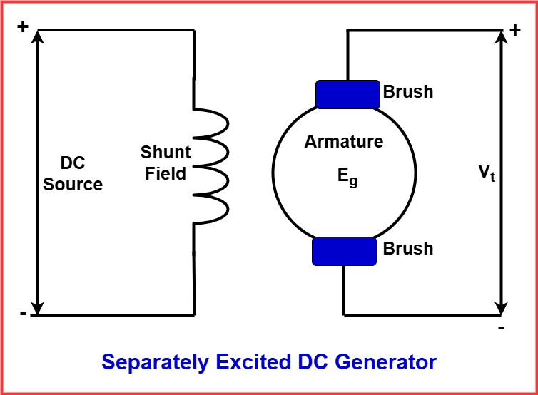
1) Separately Excited DC Generator
In a separately excited DC generator, the field coils derive their power from an external DC source, rather than from the generator itself. This allows better control over the field current and, consequently, the output voltage. These generators are commonly used in applications requiring precise voltage regulation.
2) Self-Excited DC Generator
In a self-excited DC generator, the generator itself supplies the current needed for field excitation. The initial emf generation occurs due to residual magnetism in the field poles. This induced emf causes a small current to flow in the field windings, which gradually strengthens the magnetic field and increases the generated voltage.
Self-excited DC generators are further classified into three types:
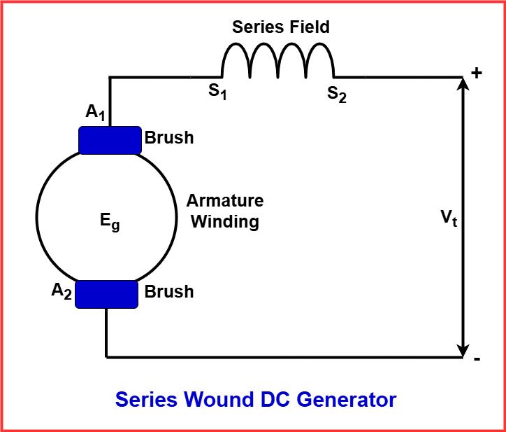
(a) Series Wound DC Generator
The field winding is connected in series with the armature winding. This type is suitable for applications requiring high current and variable voltage output.
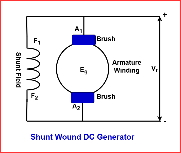
(b) Shunt Wound DC Generator
The field winding is connected in parallel with the armature winding, ensuring a relatively stable output voltage. These are widely used in battery charging and lighting systems.
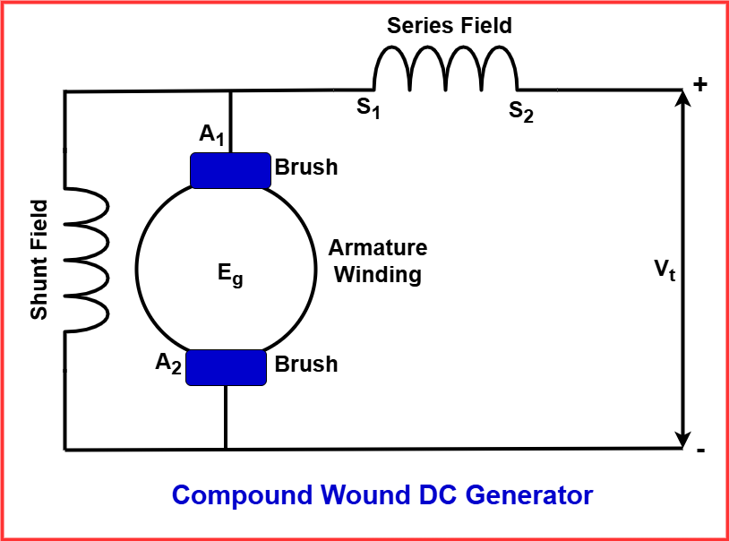
(c) Compound Wound DC Generator
This type combines both series and shunt field windings, offering the advantages of both. Compound wound generators are used in industrial applications requiring a stable voltage with variable load conditions.
Each type of DC generator has specific advantages and applications, making them suitable for different electrical systems and industrial needs.
Advantages of DC Generators
DC generators offer several benefits, making them a preferred choice in various applications:
- High Power Output – DC generators can generate a substantial amount of electrical power.
- Strong Load Capacity – They can efficiently handle significant loads at their terminals.
- Simple Construction – The design and construction of DC generators are straightforward, making them easy to manufacture and maintain.
- Unequal Power Distribution – These generators are useful for applications requiring uneven distribution of output power.
- High Efficiency – With efficiency levels ranging between 85% and 95%, they ensure minimal energy loss.
- Stable Output Voltage – DC generators provide a steady and consistent power output, making them reliable for sensitive applications.
- Compact and Lightweight – They are relatively small and lightweight, making them easy to transport and install.
Due to these advantages, DC generators are widely used in various industries, including power backup systems, battery charging, and traction applications.
Disadvantages of DC Generators
Despite their advantages, DC generators have several drawbacks:
- Incompatibility with Transformers – DC generators cannot be used with transformers, limiting their voltage conversion capabilities.
- Various Energy Losses – They suffer from copper losses, mechanical losses, and eddy current losses, reducing overall efficiency.
- Voltage Drop Over Long Distances – DC power transmission experiences significant voltage drops, making it inefficient for long-distance applications.
- Complex Design – The presence of a split-ring commutator complicates the design and construction of the generator.
- High Cost – DC generators are more expensive compared to their AC counterparts due to additional components like commutators and brushes.
- High Maintenance Requirements – Regular maintenance is necessary to ensure proper functioning, as brushes and commutators wear out over time.
- Sparking Issues – During energy generation and transmission, sparks are produced, leading to energy loss and potential hazards.
Due to these disadvantages, DC generators are often replaced by AC generators in modern power generation systems, except in specialized applications.
Applications of DC Generators
DC generators are widely used in various applications based on their types:
- Separately Excited DC Generators – Used for boosting voltage and in electroplating applications. They also supply power for lighting using a field regulator.
- Self-Excited (Shunt) DC Generators – Commonly used for electricity generation and general illumination. They are also suitable for battery charging applications.
- Series DC Generators – Employed in arc lighting, as a steady current generator, and as a voltage booster in power transmission.
- Compound DC Generators – Used to power DC welding equipment, ensuring a stable and consistent voltage supply.
- Level Compound DC Generators – Provide electricity for hostels, hotels, and offices, where a stable power source is needed.
- Voltage Compensation in Feeders – DC generators help compensate for voltage drops in long-distance feeders, improving power transmission efficiency.
These applications highlight the versatility of DC generators in industrial, commercial, and specialized electrical systems.
Difference Between AC Generator and DC Generator
| S.No | AC Generator | DC Generator |
|---|---|---|
| 1 | Converts mechanical energy into alternating current (AC). | Converts mechanical energy into direct current (DC). |
| 2 | Simple structure. | More complex due to the presence of commutators and brushes. |
| 3 | The current flow reverses periodically. | The current flows in only one direction. |
| 4 | Classified into single-phase, three-phase, synchronous, and induction generators. | Classified into separately excited and self-excited generators. |
| 5 | Generates high voltage output. | Generates low voltage output. |
| 6 | No commutators are required. | Uses commutators to maintain unidirectional current flow. |
| 7 | More expensive than DC generators. | Less expensive compared to AC generators. |
| 8 | Highly efficient due to smooth slip rings. | Less efficient because commutators and brushes wear out quickly. |
| 9 | Lower risk of short circuits due to efficient brushes. | Higher risk of short circuits due to wear and tear of commutators and brushes. |
| 10 | Armature is always the rotor. | Armature can be either the stator or rotor. |
| 11 | Low maintenance requirement. | Requires frequent maintenance. |
| 12 | Output can be easily transmitted using transformers. | Difficult to transmit output due to the absence of transformers. |
| 13 | Current is induced in either the stator or rotor. | Current is induced in the rotor only. |
| 14 | Used in home appliances, micro motors, and industrial power supply. | Used for large electric motors, subway systems, and industrial applications. |
- AC generators are more efficient, require less maintenance, and are ideal for power distribution.
- DC generators, despite their complex design and higher maintenance needs, are crucial for specific applications like traction motors, battery charging, and electroplating.
Read Next: