Learn about cable tray width dimensions and specifications as per NEC standards. Understand types, sizes, materials, and installation guidelines for safe and efficient wiring systems
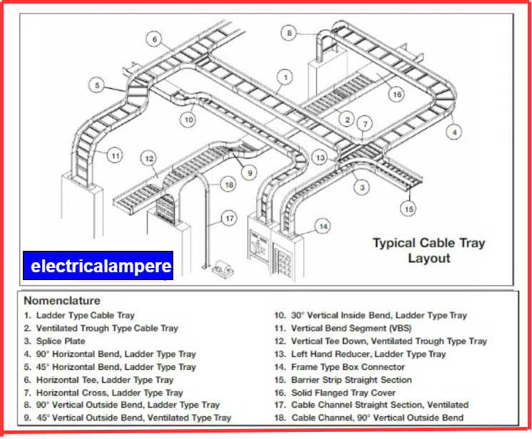
Cable tray systems are an alternative to traditional wireways and electrical conduits. Unlike electrical conduits that completely enclose and protect wires, cable trays partially support and protect and allow better ventilation and easier access to the cables. Cable trays are available in various types, including ladder, perforated, solid-bottom, and wire mesh trays. Cable trays can accommodate the following types of cables.
- High-voltage power cables.
- Power distribution cables
- Control cables
- Telecommunications cables
- Fiber Optical cables
Purpose of Cable Trays
Cable trays are components of the systems that support the cables and wires that supply electricity and communications.
Cable trays are parts of systems designed to hold and support cables and wires. These cables carry electricity and analog and digital communication signals.
A cable tray system supports and protects both power and control cables. It simplifies tasks like upgrading, expanding, reconfiguring, or moving networks. This flexibility saves time and reduces costs during maintenance or modifications.
Cable Tray norms as per the National Electrical Code (NEC)
The National Electrical Code (NEC) specifies the capacity limits for cables rated at 2000 volts or less in cable trays. Single conductor cables can operate at different maximum ampacities, depending on how they are arranged in ladder-style or ventilated cable trays. This arrangement affects how heat is managed, ensuring safe and efficient operation. Following NEC guidelines, cable trays provide flexibility for accommodating various cable types while ensuring compliance with electrical standards.
Number of multicore cables in cable tray that are under 2000 volts
(1) 4/0 AWG/Kcmil (120 Sq.mm) Cable (or) Larger Cables
Ladder cable tray: The usable interior width of the tray must be equal to the combined diameters of the cables when they are arranged in a single layer. This ensures proper cable fit and support within the tray.
Solid bottom cable tray: The total combined diameters of the cables should not exceed 90% of the available width of the cable tray. This ensures adequate space for cable placement, reduces the risk of overheating, and allows for proper cable management.
(2) Cables Smaller than 4/0 AWG/Kcmil (120 Sq.mm)
Ladder cable tray: All cables inserted in the cable tray must possess cross-sectional areas equal to or less than the tray width’s permissible cable area, as shown in the accompanying table. All cables placed in the cable tray must have cross-sectional areas that do not exceed the maximum allowable cable area for the tray width, as indicated in the following table.
Solid bottom cable tray: For cables installed in a solid bottom cable tray, the allowable cable area is reduced by 22%. This reduction accounts for the limited ventilation and heat dissipation compared to other tray types.
| Inside Width of the Cable Tray | Allowable Cable Area square inches(square millimeter) |
| 6 inches(152.5millimeter) | 7 square inches(4516 square millimeter) |
| 9 inches (228.6millimeter) | 10 square inches(6451 square millimeter) |
| 12 inches (304.8millimeter) | 14 square inches(9032 square millimeter) |
| 18 inches(457.2millimeter) | 21 square inches(13548 square millimeter) |
| 24 inches (609.6millimeter) | 28square inches(18064 square millimeter) |
(3) Cables larger than 4/0 AWG (120 Sq.mm) with Cables smaller than 4/0 AWG (120 Sq.mm)
Ladder cable tray: The ladder cable tray should be organized into two zones to accommodate different cable sizes. While a physical barrier or separator is not mandatory, it may be used for better organization. Cables sized No. 4/0 AWG and larger must occupy their zone and be arranged in a single layer to ensure proper spacing, ventilation, and heat dissipation. Smaller cables can be placed in the other zone, following standard guidelines for cable installation. This arrangement optimizes tray usage, maintains safety standards, and prevents potential overheating.
Proper cable tray: A simple method for determining the correct cable tray width is to calculate the cable tray widths needed for each of the cable configurations per steps (2) and (3). Then sum the widths to determine the required cable tray width.
Proper cable tray: To select the appropriate cable tray width, follow the following method:
- Calculate the required cable tray width for each cable configuration using the steps outlined in (2) and (3).
- Sum the calculated widths from all configurations to determine the required cable tray width.
(4) Multi conductor Control & Signal Cables
Ladder cable tray: When using a ladder cable tray exclusively for control and signal cables, the total allowable cable area can occupy up to 50% of the tray’s cross-sectional area.
Solid bottom cable tray: When using a solid bottom cable tray, the allowable cable fill is limited to 40% of the tray’s cross-sectional area, a reduction from the 50% permitted in other tray types.
Number of single-conductor cables in the cable tray that are not greater than 2000 volts (NEC-392.12)
Single-conductor cables intended for installation in a cable tray must be larger than 1/0 AWG (53.5 sq. mm). Additionally, solid-bottom cable trays are not permitted for this type of installation.
(1) Cables with a cross-sectional area of 500 square millimeters or larger
The combined diameters (Σd) of all single conductor cables to be installed must not exceed the width of the cable tray, as specified in the table below.
| Inside the Width of the Cable Tray | Allowable Cable Area( square inches/ square millimeter) |
| 6 inches (152.5 millimeter) | 6.5 square inches (4194 square millimeters) |
| 9 inches (228.6 millimeters) | 9.15 square inches (6129 square millimeters) |
| 12 inches (304.8 millimeter) | 13 square inches (8387 square millimeters) |
| 18 inches (457.2 millimeter) | 19 square inches (12258 square millimeters) |
| 24 inches (609.6 millimeters) | 26square inches (16774 square millimeter) |
| 30inches(762millimeter) | 32.5square inches (20968 square millimeters) |
| 36 inches (914.5millimeter) | 39square inches (25161square millimeter) |
(2) Cables ranging from 250 kcmil (120 square millimeters) to 1000 kcmil (500 square millimeters)

As detailed in the following table, the total cross-sectional area of all single conductor cables placed in the cable tray must not exceed the allowable cable area for the tray width.
| Inside the Width of the Cable Tray | Allowable Cable Area (square inches/ square millimeter) |
| 6 inches (152.5 millimeter) | 6.5 square inches (4194 square millimeters) |
| 9 inches (228.6 millimeters) | 9.15 square inches (6129 square millimeters) |
| 12 inches (304.8 millimeter) | 13 square inches (8387 square millimeters) |
| 18 inches (457.2 millimeter) | 19 square inches (12258 square millimeters) |
| 24 inches (609.6 millimeters) | 26 square inches (16774 square millimeters) |
| 30 inches (762 millimeters) | 32.5 square inches (20968 square millimeters) |
| 36 inches (914.5 millimeters) | 39 square inches (25161 square millimeters) |
(3) Cables larger than 1000 Kcmil (500 Sq.mm) installed with cables smaller than 1000 Kcmil (500 Sq.mm)
The total cross-sectional area of all single-conductor cables placed in the cable tray must be equal to or less than the allowed cable area for the tray width. This is shown in the table below.
| Inside Width of the Cable Tray | Allowable Cable Area square inches (square millimeter) |
| 6 inches (152.5 millimeter) | 6.5 square inches (4194 square millimeters) |
| 9 inches (228.6 millimeters) | 9.15 square inches (6129 square millimeters) |
| 12 inches (304.8 millimeter) | 13 square inches (8387 square millimeters) |
| 18 inches (457.2 millimeter) | 19 square inches (12258 square millimeters) |
| 24 inches (609.6 millimeters) | 26 square inches (16774 square millimeters) |
| 30 inches (762 millimeters) | 32.5 square inches (20968 square millimeters) |
| 36 inches (914.5 millimeters) | 39 square inches (25161 square millimeters) |
(4) Single-conductor cables ranging from 1/0 (50 sq. mm) to 4/0 (120 sq. mm)
Single-conductor cables ranging from 1/0 (50 sq. mm) to 4/0 (120 sq. mm) should be installed in a single layer.
This method may have issues with individual conductors in the cable tray wiring system. To avoid problems from uneven voltages, the conductors should be tied together. If a neutral conductor is used, it should be bundled with all three-phase conductors.
Tray width for single-conductor size cables:
- 1/0AWG (50 square millimeter)
- 101520312/0AWG (70square millimeter)
- 91419293/0AWG(9550square millimeter)
- 81317264/0AWG (120square millimeter)
- 8121625/0kcmill (120square millimeter)
- 11182435/0kcmill (185square millimeter)
- 9141950/0kcmill (240square millimeter)
- 7111475/0kcmill(400square millimeter)
- 5810100/0kcmill (500square millimeter)
Number of Cables in the Cable Tray that are greater than 2.1 KV
The combined diameter of all cables with a voltage rating of 2001 volts or more must not exceed the width of the cable tray.
(1). Minimum Requirements for Barriers (NEC 392.6)
- When the single-core cable above and below 600 volts are installed in the same tray, a barrier is placed between them to separate the cable system.
- Barriers are required If multi-core cables with voltages above 600 volts are installed in the same cable tray as cables with 600 volts or less.
- The barriers must be made from the same material as the cable tray and should have a height similar to the cable tray.